LED light source improvement method and LED light source

A technology of LED light sources and LED lamp beads, which is applied in the field of LED light sources, can solve the problems of low utilization rate of LED lamp beads and poor uniformity of light sources, and achieve the effect of increasing utilization rate and improving uniformity

Active Publication Date: 2013-07-31
SOUTH CHINA UNIV OF TECH +1
View PDF6 Cites 1 Cited by
  • Summary
  • Abstract
  • Description
  • Claims
  • Application Information

AI Technical Summary

Problems solved by technology

[0005] The present invention aims at the shortcomings of existing LED light sources such as low utilization rate of LED lamp beads and poor uniformity of light source, and pr

Method used


Image

  • LED light source improvement method and LED light source
  • LED light source improvement method and LED light source
  • LED light source improvement method and LED light source

Examples


Embodiment 1

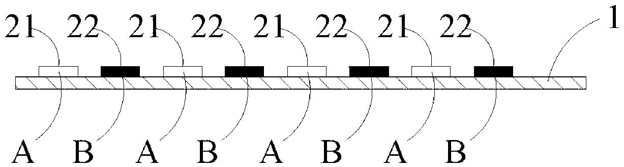
[0025] In the design of LCD backlight modules, usually based on the minimum brightness and central chromaticity requirements required by the backlight module, the minimum required LED light source can be easily estimated by considering factors such as the brightness enhancement factor of the optical film and the light loss of the light guide plate. The total brightness and central chromaticity, and then divided by the total number of LED lamps arranged under ideal conditions, can estimate the minimum brightness and central chromaticity requirements of each LED lamp bead, assuming that the minimum brightness of the LED lamp bead is required to be L=36LM, center color coordinates (x,y)=(0.26,0.22). At present, the common practice of backlight modules is to use LED lamp beads of the same specification with the minimum brightness of L=36LM and the center color coordinates (x, y)=(0.26, 0.22) to be arranged at equal intervals, resulting in LED lamp bead utilization. Low, poor unifo...

Embodiment 2

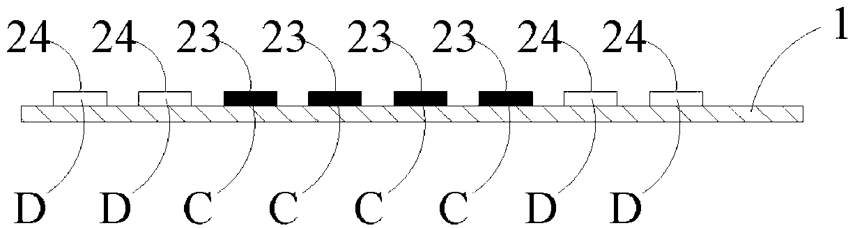
[0035] Please refer to figure 2 The difference between this embodiment and the first embodiment is that in order to improve the light uniformity of the backlight module, the brightness of each LED light bead on the substrate 1 when it is working normally is changed from the light-emitting area located in the center of the substrate to the peripheral area located on the substrate. The luminescent area increases sequentially. In this embodiment, the LED lamp beads of the two kinds of specifications adopt the brightness L 1 =35LM, color coordinates (x 1 ,y 1 )=(0.27,0.23) LED lamp bead 23 and brightness L 2 =37LM, color coordinates (x 2 ,y 2 )=(0.25,0.21) LED lamp bead 24. Divide the substrate 1 into 8 light-emitting areas connected in parallel, and the same light-emitting area is provided with LED lamp beads with the same specifications; the four light-emitting areas located in the center are provided with LED lamps with relatively low luminance during normal operation B...

Embodiment 3

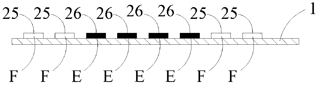
[0038] Please refer to image 3 The difference between this embodiment and the second embodiment is that in order to improve the central brightness of the backlight module, the brightness of each LED lamp bead on the substrate 1 when it is working normally is changed from the light-emitting area located in the center of the substrate to the LED lamp beads located in the peripheral area of ​​the substrate. The luminous area decreases successively. In this embodiment, the LED lamp beads of the two kinds of specifications adopt the brightness L 1 =35LM, color coordinates (x 1 ,y 1 )=(0.27,0.23) LED lamp bead 25 and brightness L 2 =37LM, color coordinates (x 2 ,y 2 )=(0.25,0.21) LED lamp bead 26. Divide the substrate 1 into 8 light-emitting areas connected in parallel, and the same light-emitting area is provided with LED lamp beads with the same specifications; the four light-emitting areas located in the center are provided with LED lamps with relatively high luminous brig...


PUM


Abstract

The invention provides an LED light source improvement method. According to the method, LED lamp beads with at least two different specification parameters are arranged on a substrate in a mixing manner. Based on the LED light source improvement method, a provided breakthrough concept is that the LED lamp beads with different specification parameters are arranged on the same substrate so as to improve the utilization ratio of the LED lamp beads and improve the luminous uniformity of a whole LED light source. Moreover, according to the method, the LED lamp beads with at least two different specification parameters are mixedly arranged in a different manner, so that the whole LED light source can meet the use requirements of specification parameters after being mixed, the luminous uniformity of the whole LED light source is better, and the problems of discreteness of the LED lamp bead specification parameters and uneven lighting of the LED light source in a current LED preparation technology are solved.

Description

technical field [0001] The invention belongs to the field of LED light sources, in particular to a method for improving the LED light source and the LED light source. Background technique [0002] At present, due to the limitations of the LED manufacturing process, the specifications and parameters of the produced LED lamp beads have a certain degree of discreteness, and the human eye is more sensitive to color and brightness, and the direct use of unsorted LEDs is prone to uneven phenomena, which affects to the visual effect of the irradiated object. For example, in a liquid crystal display device, LEDs are generally used as the backlight source of the backlight module in the liquid crystal display device. In addition, sorted LEDs of the same specification are generally arranged evenly at equal intervals. Since the brightness of the middle area is the superposition of the brightness of other surrounding areas, and LED is a point light source, the brightness distribution de...

Claims


Application Information

Patent Timeline
IPC IPC(8): F21V19/00F21Y101/02F21Y113/13F21Y115/10
Inventor 周忠伟彭俊彪
Owner SOUTH CHINA UNIV OF TECH
Why Eureka
Try Eureka