Device for cooling machine room and method for adjusting cooling air supply

A technology for computer rooms and air supply chambers, applied in heating methods, space heating and ventilation, heating and ventilation control systems, etc., can solve the problem of low utilization rate of cold air flow in areas where high-power IT equipment is distributed, and cannot achieve cooling air supply volume Refined control and other issues to achieve efficient utilization

Active Publication Date: 2016-01-13
HUAWEI DIGITAL POWER TECH CO LTD
View PDF6 Cites 0 Cited by
  • Summary
  • Abstract
  • Description
  • Claims
  • Application Information

AI Technical Summary

Problems solved by technology

[0004] In the actual working process, the above-mentioned enhanced air supply floor device still cannot realize more refined control of the cooling air supply volume, and there is still a phenomenon that the utilization rate of the cold air flow is not high in the distribution area of ​​high-power IT equipment

Method used


Image

  • Device for cooling machine room and method for adjusting cooling air supply
  • Device for cooling machine room and method for adjusting cooling air supply
  • Device for cooling machine room and method for adjusting cooling air supply

Examples


Embodiment 1

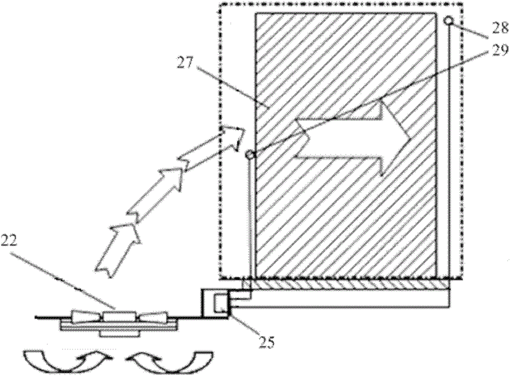
[0055] Please refer to the attached figure 2 , This figure shows a schematic diagram of a device for cooling a machine room.

[0056] The device for cooling a computer room provided in the embodiment of the present invention is applied to a cooling system of a cabinet in the computer room, and includes:

[0057] The fan 22 is used to convey the cold air flow and is the power source for the cold air flow in the entire cooling device room;

[0058] The temperature sensor is arranged on the cabinet 27 for detecting temperature. The temperature sensor includes air inlets respectively arranged on the cabinet 27, a first temperature sensor 29 for detecting the temperature of the air inlet area of ​​the cabinet 27 and an outlet provided on the cabinet 27. An air outlet, a second temperature sensor 28 used to detect the temperature of the air outlet area of ​​the cabinet 27;

[0059] The controller 25 is connected to the first temperature sensor 29, the second temperature sensor 28, and the ...

Embodiment 2

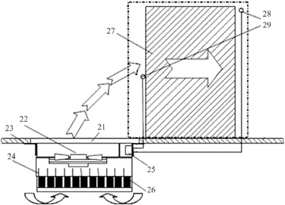
[0085] Please refer to the attached Figure 5 , This figure is a schematic structural diagram of a device for cooling a machine room provided in the second embodiment of the present invention.

[0086] The device for cooling a computer room provided in the embodiment of the present invention is applied to a cooling system of a computer room and includes:

[0087] The fan 22 is used to convey the cold air flow and is the power source for the cold air flow in the entire cooling equipment room;

[0088] The temperature sensor is arranged on the cabinet 27 for detecting temperature. The temperature sensor includes an air inlet arranged on the cabinet 27 for collecting the temperature T of the air inlet in The first temperature sensor 29 is arranged at the air outlet of the cabinet 27 and is used to collect the temperature T of the air outlet out The second temperature sensor 28 is arranged on the top of the air outlet of the cabinet 27 and is used to collect the temperature T at the top...


PUM


Abstract

The invention provides a machine room cooling device which comprises a fan, a temperature sensor arranged on a cabinet, and a controller connected with the temperature sensor and used for controlling the rotational speed of the fan, wherein the temperature sensor comprises a first temperature sensor and a second temperature sensor arranged at the air inlet and the air outlet of the cabinet; the controller is used for decreasing the rotational speed of the fan when the detected temperature difference value of the second temperature sensor and the first temperature sensor is smaller than the minimum value of a set interval; or the controller is used for increasing the rotational speed of the fan when the detected temperature difference value of the second temperature sensor and the first temperature sensor is larger than the maximum value of the set interval. The machine room cooling device achieves more precious adjustment of the cooling air supply amount, and achieves more efficient utilization of the cold airflow. The invention further provides a cooling air supply adjusting method.

Description

Technical field [0001] The present invention relates to the technical field of equipment cooling, and more specifically, provides a device for cooling a machine room. The present invention also provides a method for applying the above-mentioned device for cooling a machine room for cooling and air supply adjustment. Background technique [0002] There are a large number of IT equipment in the communication room. In order to ensure the normal operation of the IT equipment in the communication room, the IT equipment in the communication room needs to be cooled. [0003] The prior art provides a reinforced air supply floor device with a structure such as figure 1 As shown, the reinforced air supply floor device adopts the EC fan 14 arranged in the housing 15 for forced air supply, and the cold air flows out of the floor 13 after being guided by the adjustable air valve plate 11. Among them: the control of the EC fan 14 The device 12 can adjust the speed of the EC fan 14 according to t...

Claims


Application Information

Patent Timeline
Patent Type & Authority Patents(China)
IPC IPC(8): F24F11/02F24F11/00
Inventor 黄文雄
Owner HUAWEI DIGITAL POWER TECH CO LTD
Why Eureka
Try Eureka