Parking system and method for taking vehicle

A parking system and vehicle technology, which is applied in the field of parking systems and the vehicles used to achieve the requirements of reducing motion accuracy or travel detection accuracy and improving reliability

Inactive Publication Date: 2013-09-25
佛山市南海区爱满亭机械有限公司
View PDF4 Cites 7 Cited by
  • Summary
  • Abstract
  • Description
  • Claims
  • Application Information

AI Technical Summary

Problems solved by technology

[0012] The purpose of the present invention is to solve the problem of intensive parking

Method used


Image

  • Parking system and method for taking vehicle
  • Parking system and method for taking vehicle
  • Parking system and method for taking vehicle

Examples


Embodiment 1

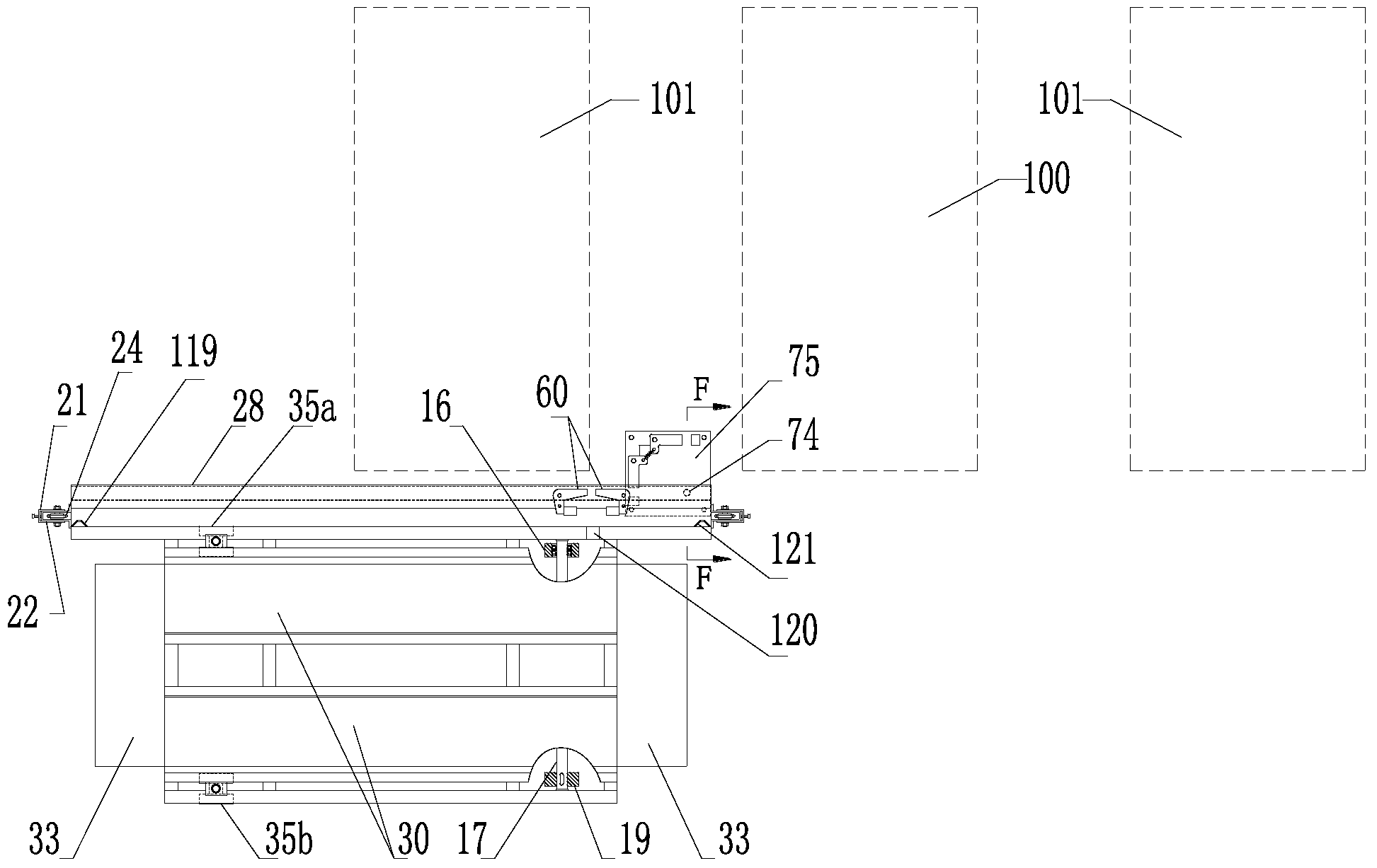
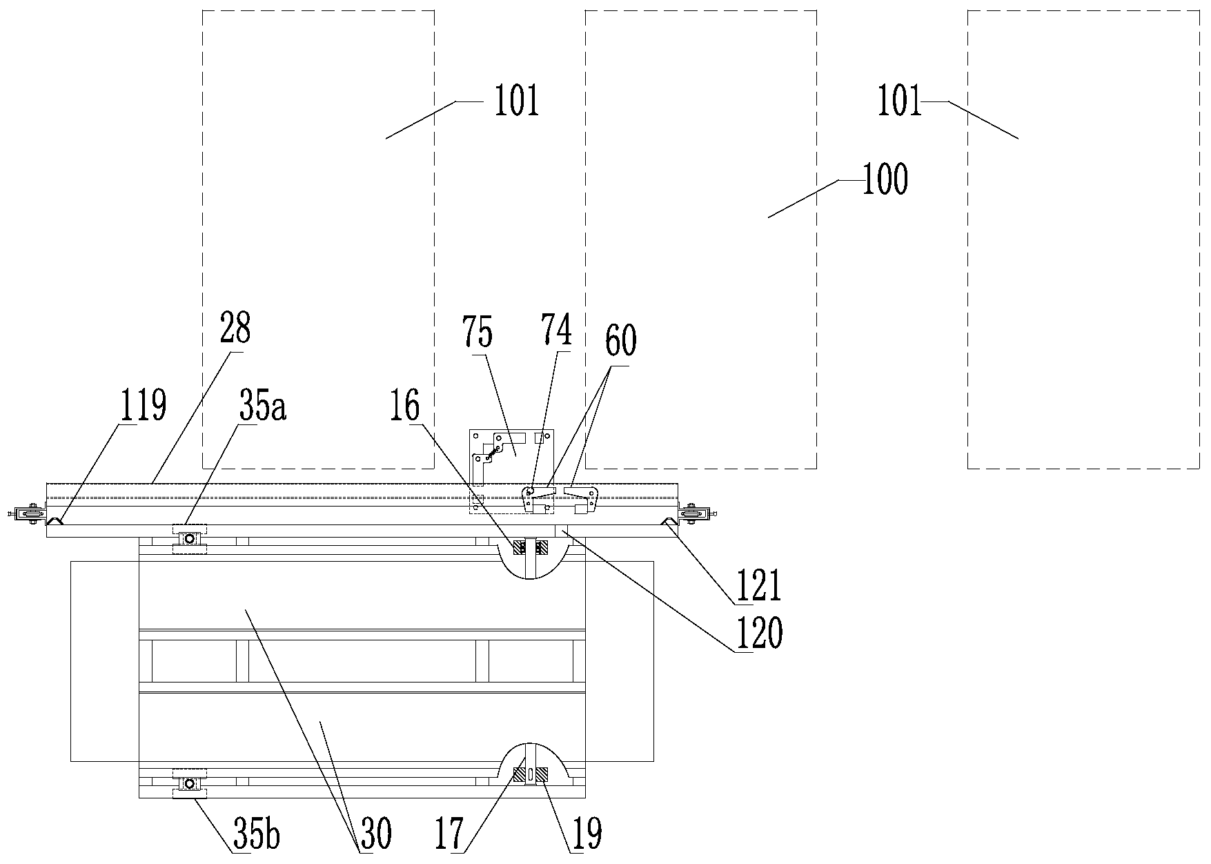
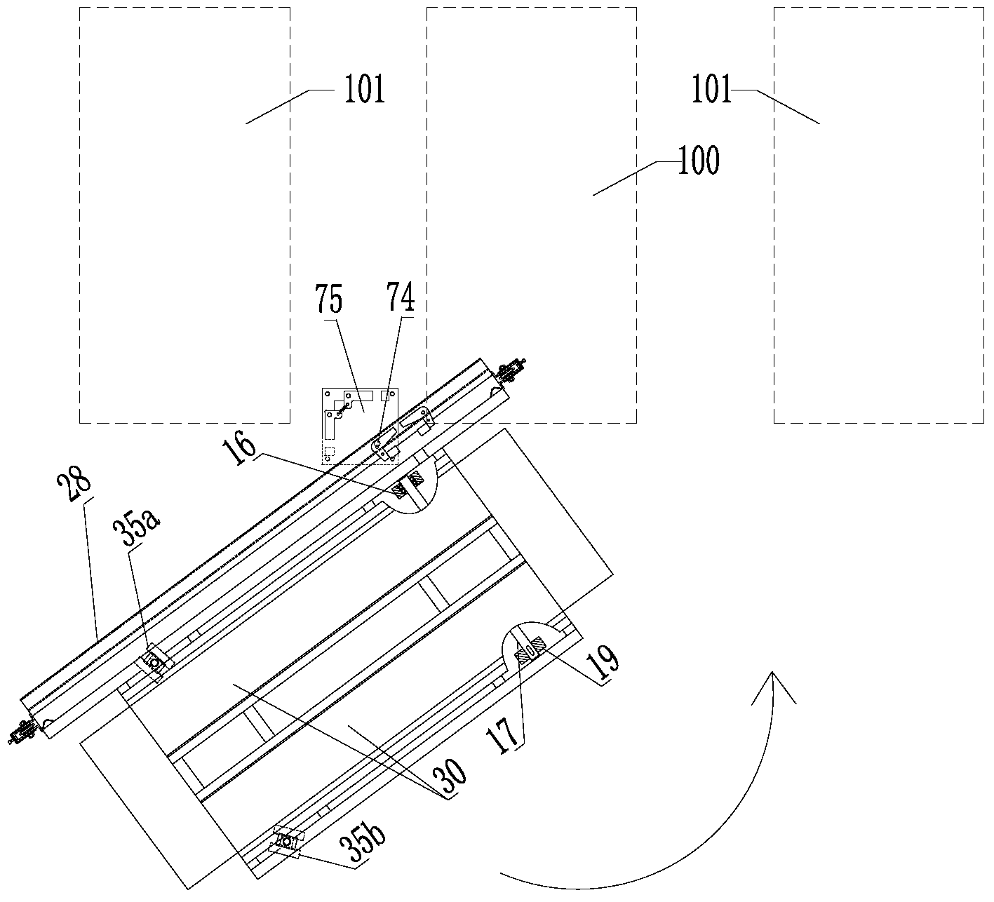
[0087] Embodiment one ( Figure 1 to Figure 25 )

[0088] Such as Figure 1 to Figure 5 As mentioned above, it is a schematic diagram of the structure of the supporting plate supporting the vehicle entering the parking space. The process is reversible, that is, the vehicles in the parking space can also be taken out in the reverse order as shown in the figure. Figures 1 to 5 In, the drawing of the part above the swing block 73 of the power head device is omitted, and only the base part of the power head device is reserved.

[0089] The invention is a horizontal carrier for parking on the ground, which can realize the secondary translation and 90° rotation of the parked trolley according to the most extensive and reasonable movement mode, and temporarily borrows the public aisle to give way to the access and space for the second floor. Or access by the car inside, so as to increase the parking density.

[0090] In terms of use occasions in this embodiment, T-shaped passage ...

Embodiment 2

[0143] Embodiment two ( Figure 26 to Figure 27 )

[0144] Such as Figure 26 to Figure 27 As shown, it is the second embodiment, which differs from the first embodiment in that the driving structure for driving the steering wheel to rotate is different.

[0145] A first steering wheel 35a and a second steering wheel 35b are mounted on the other end of the load plate 30 near the roadside. When the bearing plate 30 moves linearly, the reduction motor 134 rotates forward, and the chain 130 is driven to move rightward to the limit position through the sprocket 132 . The wire rope 46 is pulled to the clockwise limit position by the connecting piece 133 . Because wire rope 46 is the connection of closure, and by the restriction of 4 groups of pulley shafts 44 and pulley 45, wire rope 46 passes through rope buckle 43, pin 42, crank 41 and rope buckle 47,, pin 48, crank 49, respectively makes the first The steering wheel 35a and the second steering wheel 35b keep in line with the...

Embodiment 3

[0149] Embodiment three ( Figure 28 to Figure 29 )

[0150] Such as Figure 28 to Figure 29 As shown, it is the third embodiment, which differs from the first embodiment in that the driving structure for driving the steering wheel to rotate is different.

[0151] Turning wheels 35a, 35b are installed at the other end of the load plate 30 near the roadside. When the bearing plate 30 moves linearly, the reduction motor 134 rotates forward, and the gear 144 drives the rack 145 to move to the left to the limit position. By pin 141, connecting rod 140, pin 42, crank 41 and pin 143, connecting rod 142, pin 48, crank 49, respectively make turning wheel 35a, 35b keep consistent with power wheel 19, supporting wheel 15 directions simultaneously.

[0152] When the bearing plate 30 swings horizontally around the fixed axis, the reduction motor 134 reverses, and the gear rack 145 is driven to the right by the gear 144 to move to the limit position. The rod 142, the pin 48, and the cr...


PUM


Abstract

The invention discloses a parking system. The parking system comprises a bearing plate and a power head device, wherein multiple wheels are arranged at the lower side of the bearing plate; the power head device which is used for driving the bearing plate to move comprises a base, a swinging block, a driving motor and a control motor; the base is fixed on a floor; the swinging block is arranged on the base and is rotationally connected to the base; the driving motor and the control motor are fixed on the swinging block; the control motor is used for locking or releasing relative displacement of both the bearing plate and the driving motor; when the control motor releases the bearing plate, the driving motor drives the bearing plate to do translational motion, with respect to the driving motor per se; when the control motor locks the bearing plate, the driving motor drives the bearing plate to rotate around a rotating shaft line at a joint of the swinging block and the base, and the swinging block rotates synchronously along with the bearing plate. The invention also discloses a method for taking a vehicle.

Description

technical field [0001] The invention belongs to the technical field of mechanical parking equipment, and in particular relates to a parking system and a method for picking up a vehicle. Background technique [0002] In the related field of parking mode, in the traditional parking lot mode, the parking space is planned on the ground in advance, and the vehicle can directly drive into the parking space according to the instructions of the parking space to complete the parking process. This traditional parking management method has the advantages of convenience, simplicity, and extremely low cost, but it requires a larger parking space and a wider aisle to meet the space requirements for vehicles to complete the parking process. [0003] For metropolises where land is very expensive, parking is a headache for many car owners. The city’s ability to manage parking in public places has also reached a limit. How to meet the needs of more and more vehicles in a smaller and smaller s...

Claims


Application Information

Patent Timeline
IPC IPC(8): E04H6/14E04H6/06
Inventor 梁代平
Owner 佛山市南海区爱满亭机械有限公司
Why Eureka
Try Eureka