Grinding device and grinding equipment

A technology of grinding discs and fixing seats, which is applied in the direction of grinding drive devices, grinding/polishing equipment, metal processing equipment, etc., can solve the problems of high labor intensity, low operation efficiency, large noise and dust pollution on site, and achieve good The effect of damping and buffering, ensuring the quality of grinding, and reducing the cost of grinding

Active Publication Date: 2022-03-01
GUANGDONG BOZHILIN ROBOT CO LTD
View PDF10 Cites 0 Cited by
  • Summary
  • Abstract
  • Description
  • Claims
  • Application Information

AI Technical Summary

Problems solved by technology

[0002] At present, there is no fully automatic grinding equipment or robot grinding device for indoor concrete walls in the industry. Traditional grinding operations are performed manually with hand-held electric grinding tools.
Hand-held grinding tools are manually pressed against the wall for grinding, which is labor-intensive and has a low level of automation, and it is all manually adjusted to adapt to uneven walls. The work efficiency is low, the site noise and dust pollution are large, and it is easy to cause harm to the human body.
[0003] Secondly, although some grinding devices for grinding operations have a floating function, most of these grinding devices with a floating function can only float in a single direction, resulting in that the grinding disc cannot be adaptively pressed against the uneven wall surface. Unsuitable for grinding concrete walls

Method used


Image

  • Grinding device and grinding equipment
  • Grinding device and grinding equipment
  • Grinding device and grinding equipment

Examples


Embodiment Construction

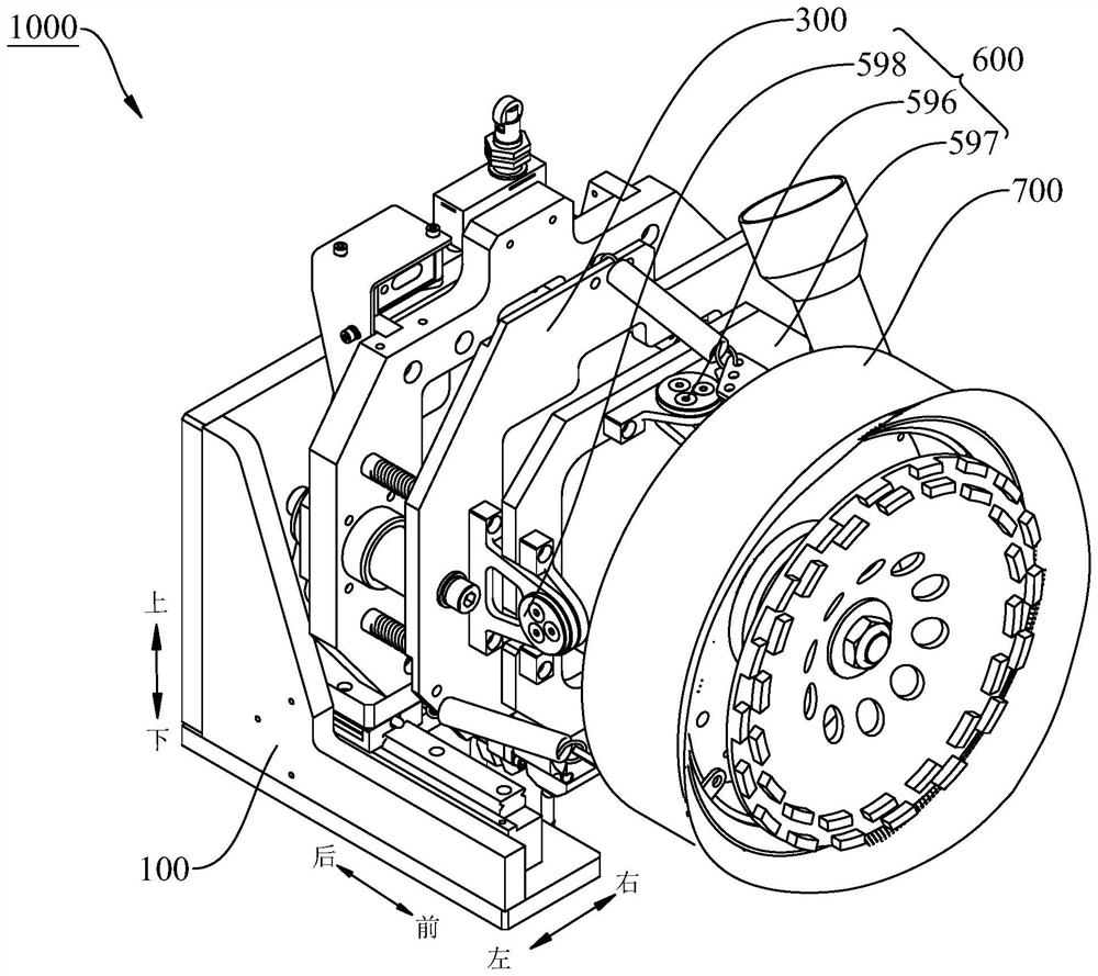
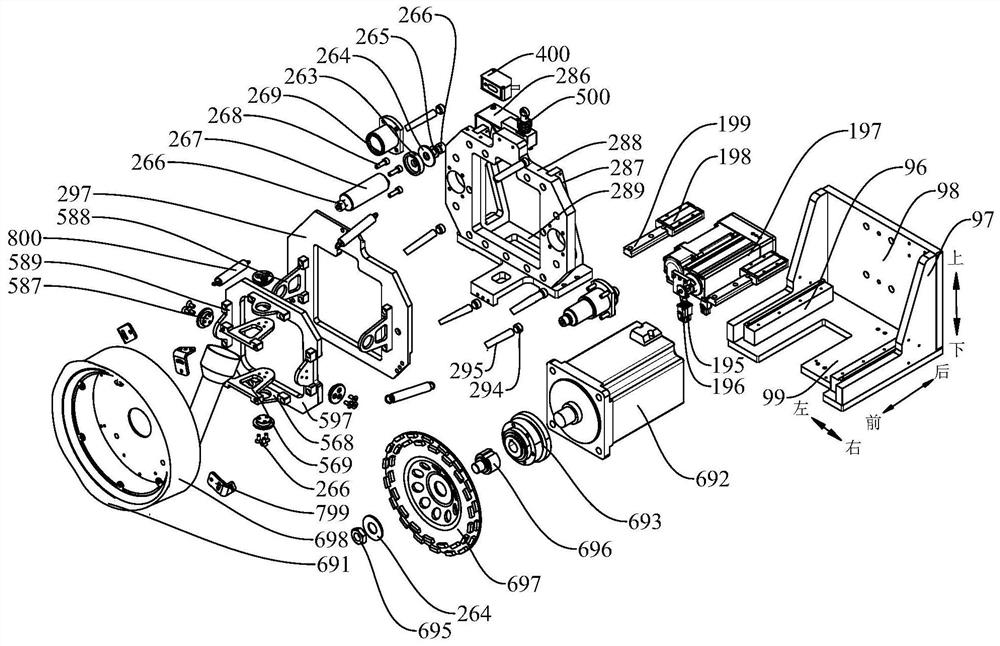
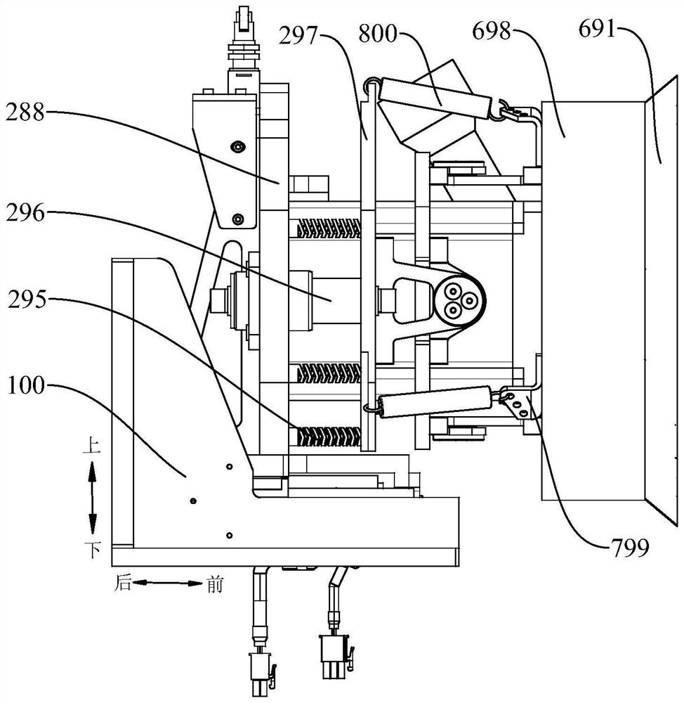
[0035] Embodiments of the present invention are described in detail below, examples of which are shown in the drawings, wherein the same or similar reference numerals designate the same or similar elements or elements having the same or similar functions throughout. The embodiments described below by referring to the figures are exemplary only for explaining the present invention and should not be construed as limiting the present invention.

[0036] In describing the present invention, it should be understood that the terms "center", "longitudinal", "transverse", "length", "width", "thickness", "upper", "lower", "front", " Rear", "Left", "Right", "Vertical", "Horizontal", "Top", "Bottom", "Inner", "Outer", "Axial", "Radial", "Circumferential" The orientation or positional relationship indicated by etc. is based on the orientation or positional relationship shown in the drawings, and is only for the convenience of describing the present invention and simplifying the descriptio...


PUM


Abstract

The invention discloses a grinding device and grinding equipment. The grinding device comprises: a base; a floating mechanism, which is arranged on the base and can float back and forth along the grinding feeding direction; a grinding assembly, which is used for grinding the working surface; Follow-up mechanism, follow-up mechanism includes a first pivot, a second pivot, a follower plate, one end of the first pivot is connected with the follower plate and the other end is connected with the grinding assembly, so that the grinding assembly can rotate around the first One end of the second pivot member is connected to the follower plate and the other end is connected to the floating mechanism, so that the follower plate can rotate around the second direction, wherein the second direction is perpendicular to the first direction. The invention reduces the vibration caused by the grinding operation through the floating mechanism, improves the adaptability to the unevenness of the wall surface, realizes that the grinding device always presses the wall surface through the follow-up mechanism, and improves the working efficiency.

Description

technical field [0001] The invention relates to the technical field of construction equipment, in particular to a grinding device and grinding equipment. Background technique [0002] At present, there is no fully automatic grinding equipment or robot grinding device for indoor concrete walls in the industry. Traditional grinding operations are performed manually with hand-held electric grinding tools. Hand-held grinding tools are manually pressed against the wall for grinding, which is labor-intensive and has a low level of automation. It is entirely manual adjustment to adapt to uneven walls. The work efficiency is low, and the site noise and dust pollution are large, which is likely to cause harm to the human body. [0003] Secondly, although some grinding devices for grinding operations have a floating function, most of these grinding devices with a floating function can only float in a single direction, resulting in that the grinding disc cannot be adaptively pressed ag...

Claims


Application Information

Patent Timeline
Patent Type & Authority Patents(China)
IPC IPC(8): B24B7/18B24B41/00B24B47/20B24B49/00B24B47/12
CPCB24B7/182B24B7/186B24B41/007B24B47/20B24B49/00B24B47/12
Inventor 张格森程德考张涛孙晋祥全鑫
Owner GUANGDONG BOZHILIN ROBOT CO LTD
Why Eureka
Try Eureka