Vehicle driving trace predicating and lane deviation evaluating method

An evaluation method and vehicle trajectory technology, applied in two-dimensional position/course control and other directions, can solve the problems of not fully considering the driver's driving behavior characteristics and differences, and achieve the effect of improving active safety and improving adaptability

Inactive Publication Date: 2006-05-24
JILIN UNIV
View PDF0 Cites 103 Cited by
  • Summary
  • Abstract
  • Description
  • Claims
  • Application Information

AI Technical Summary

Problems solved by technology

The evaluation method of the lane departure warning system mentioned above, from the perspective of image processing, uses the current state of the vehicle to judge whether the vehicle has lane departure, and does not fully consider the driving behavior characteristics of the driver, which is different from that of a real driver driving a car. There is a certain difference in the understanding of lane departure driving behavior

Method used


Image

  • Vehicle driving trace predicating and lane deviation evaluating method
  • Vehicle driving trace predicating and lane deviation evaluating method
  • Vehicle driving trace predicating and lane deviation evaluating method

Examples


Embodiment 1

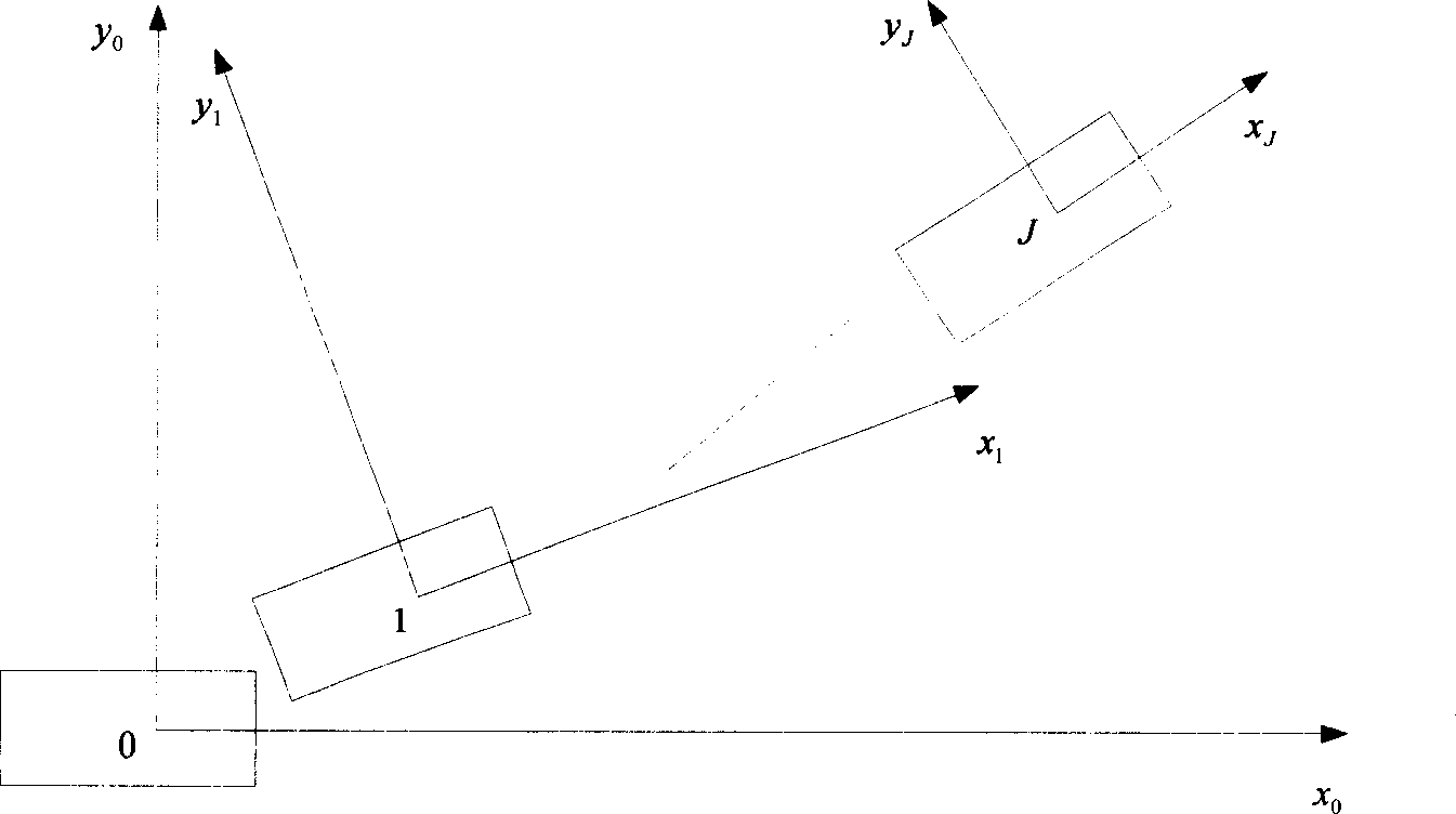
[0021] First, in step S00, the system obtains the parameters of the car at the current moment t from the on-board sensors: the longitudinal speed of the car lateral velocity Steering wheel angle δ sw , accelerator opening or brake pedal travel ratio α (when the car is in the driving condition, α is a positive value or equal to 0, indicating the accelerator opening, at this time 0%≤α≤100%; when the car is in the braking condition , α is a negative value, indicating the brake pedal travel ratio, at this time -100%≤α And the lane marking line information is in the car body coordinate system (with the center of mass of the car as the origin, the x-axis moves forward along the longitudinal axis of the car, the y-axis goes to the left, and the z-axis goes up vertically, refer to figure 2 ), so the longitudinal position x of the car at time t in the same coordinate system 0 , horizontal position y 0 and roll angle  0 are all zero.

[0022] Secondly, in step S11, according t...

Embodiment 2

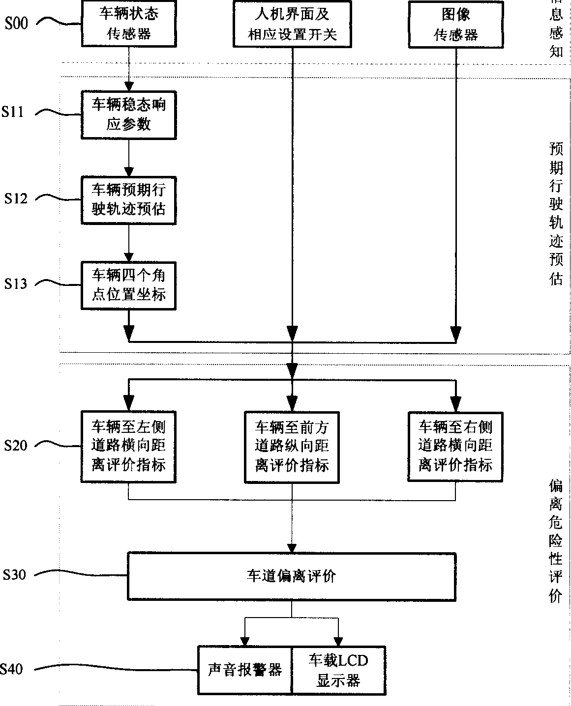
[0072] like Figure 8 As shown in the flow chart:

[0073] First, use the image sensor to collect road images, process them, and obtain the lane marking information of the road ahead. At the same time, the state parameters of the vehicle, such as speed, lane change signal, steering wheel angle, position of the accelerator pedal or brake pedal, etc., are collected through the on-board sensors to obtain the necessary input information.

[0074] Then, according to the lane-changing signal, it is judged whether the car is changing lanes. If the car is changing lanes, the system will stop working; if the car is not in the process of changing lanes, the system will use the steady-state response characteristics of the car to estimate The driving trajectory is estimated, the vehicle state parameters of the expected trajectory points are obtained, and the position coordinates of the four corners of the vehicle are calculated.

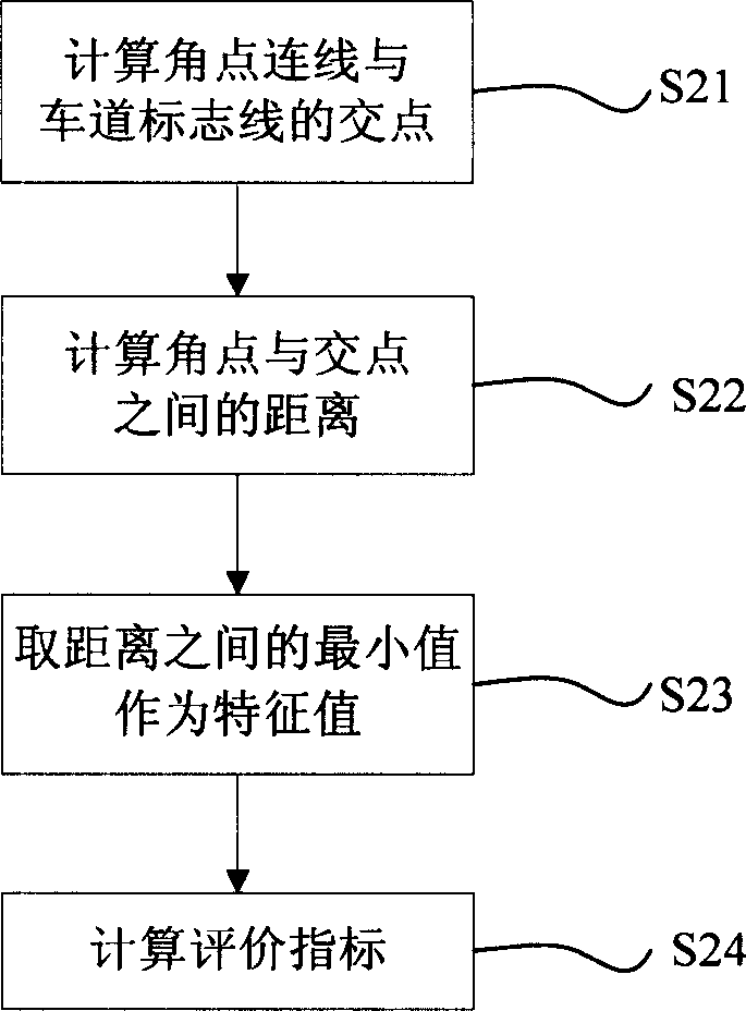
[0075] Secondly, according to the position coordinates o...


PUM


Abstract

The invention relates to a method for pre-estimating vehicle trace and evaluating lane deviation, for overcoming the defect of the existing technique not fully reflecting true behavioral characteristic of a driver, announcing a method for evaluating the danger of lane deviation based on behavioral simulation of a driver, using the image sensor-collected lane mark line information of front road and combining the vehicle sensor-provided information such as automobile speed, acceleration, and turning state, to simulate the foreseeing action of the driver (i.e. as driving, the driver controls the present driving of the automobile according to the front road information), forecasting an expected running trace of the automobile in a future period of time, and evaluating the danger of lane deviation with respect to the relative position of the expected running trace and the front road mark lines, thus judging if a lane deviation accident will happen. If the danger of the lane deviation exceeds a certain threshold value, it can give out lane deviation early warning information to the driver by sound and vehicle LCD.

Description

Technical field [0001] The invention relates to a method for estimating vehicle driving trajectory and evaluating lane departure. Background technique [0002] Traffic safety has always been one of the most concerned issues, which is directly related to the loss of people's lives and property. On the expressway, there are many traffic accidents caused by drivers' distraction or operation reasons every year, causing serious casualties and property losses. Therefore, it is of great significance to develop an intelligent assisted driving system, use the sensor system to perceive road traffic environment information for decision-making planning, provide driving suggestions to the driver or partially replace the driver for vehicle control operations. [0003] As a subsystem of the intelligent assisted driving system, the main function of the lane departure warning system is to assist the driver who is tired or monotonously driving for a long time to keep the vehicle in the lane ...

Claims


Application Information

Patent Timeline
Patent Type & Authority Applications(China)
IPC IPC(8): B60W40/00G05D1/03
Inventor 管欣高振海张立存柯斌杨得军
Owner JILIN UNIV
Why Eureka
Try Eureka