Parking system and method for taking vehicle
A technology for parking systems and vehicles, applied in the field of parking systems and vehicles used to achieve the desired effect of improving reliability, reducing motion accuracy or travel detection accuracy
- Summary
- Abstract
- Description
- Claims
- Application Information
AI Technical Summary
Problems solved by technology
Method used
Image
Examples
Embodiment 1
[0087] Embodiment one ( Figure 1 to Figure 25 )
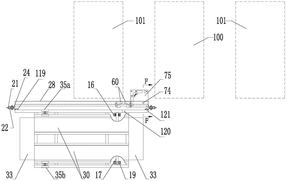
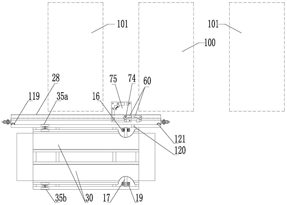
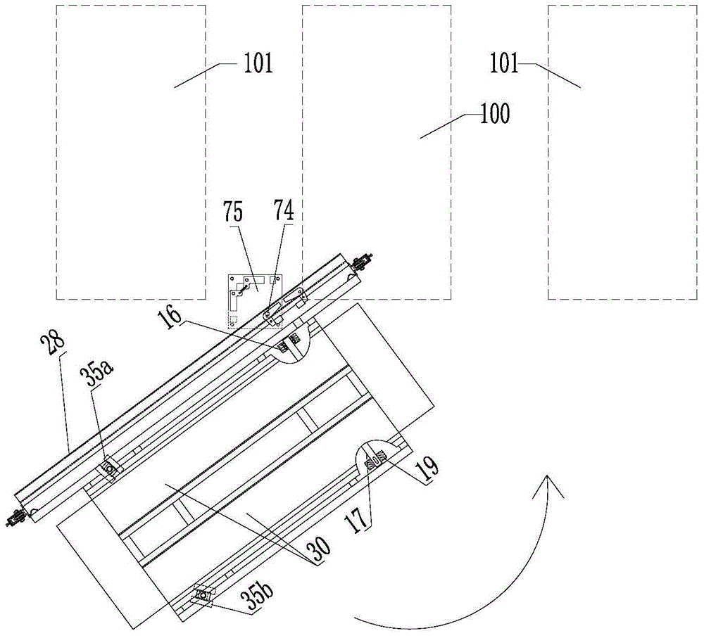
[0088] Such as Figure 1 to Figure 5 As mentioned above, it is a schematic diagram of the structure of the supporting plate supporting the vehicle entering the parking space. The process is reversible, that is, the vehicles in the parking space can also be taken out in the reverse order as shown in the figure. Figures 1 to 5 In, the drawing of the part above the swing block 73 of the power head device is omitted, and only the base part of the power head device is reserved.
[0089] The invention is a horizontal carrier for parking on the ground, which can realize the secondary translation and 90° rotation of the parked trolley according to the most extensive and reasonable movement mode, and temporarily borrows the public aisle to give way to the access and space for the second floor. Or access by the car inside, so as to increase the parking density.
[0090] In terms of use occasions in this embodiment, T-shaped passage ...
Embodiment 2
[0143] Embodiment two ( Figure 26 to Figure 27 )
[0144] Such as Figure 26 to Figure 27 As shown, it is the second embodiment, which differs from the first embodiment in that the driving structure for driving the steering wheel to rotate is different.
[0145] A first steering wheel 35a and a second steering wheel 35b are mounted on the other end of the load plate 30 near the roadside. When the bearing plate 30 moves linearly, the reduction motor 134 rotates forward, and the chain 130 is driven to move rightward to the limit position through the sprocket 132 . The wire rope 46 is pulled to the clockwise limit position by the connecting piece 133 . Because wire rope 46 is the connection of closure, and by the restriction of 4 groups of pulley shafts 44 and pulley 45, wire rope 46 passes through rope buckle 43, pin 42, crank 41 and rope buckle 47,, pin 48, crank 49, respectively makes the first The steering wheel 35a and the second steering wheel 35b keep in line with the...
Embodiment 3
[0149] Embodiment three ( Figure 28 to Figure 29 )
[0150] Such as Figure 28 to Figure 29 As shown, it is the third embodiment, which differs from the first embodiment in that the driving structure for driving the steering wheel to rotate is different.
[0151] Turning wheels 35a, 35b are installed at the other end of the load plate 30 near the roadside. When the bearing plate 30 moves linearly, the reduction motor 134 rotates forward, and the gear 144 drives the rack 145 to move to the left to the limit position. By pin 141, connecting rod 140, pin 42, crank 41 and pin 143, connecting rod 142, pin 48, crank 49, respectively make turning wheel 35a, 35b keep consistent with power wheel 19, supporting wheel 15 directions simultaneously.
[0152] When the bearing plate 30 swings horizontally around the fixed axis, the reduction motor 134 reverses, and the gear rack 145 is driven to the right by the gear 144 to move to the limit position. The rod 142, the pin 48, and the cr...
PUM
 Abstract
Description
Claims
Application Information
 - R&D
- Intellectual Property
- Life Sciences
- Materials
- Tech Scout
- Unparalleled Data Quality
- Higher Quality Content
- 60% Fewer Hallucinations
Browse by: Latest US Patents, China's latest patents, Technical Efficacy Thesaurus, Application Domain, Technology Topic, Popular Technical Reports.
© 2025 PatSnap. All rights reserved.Legal|Privacy policy|Modern Slavery Act Transparency Statement|Sitemap|About US| Contact US: help@patsnap.com


