Alternating current drive OLED (Organic Light Emitting Diode) circuit, driving method and display device

An AC drive and circuit technology, applied in static indicators, instruments, etc., can solve problems such as uneven display and OLED aging, and achieve the effects of improving compound efficiency, prolonging service life, and easy circuit operation.

Active Publication Date: 2015-06-17
BOE TECH GRP CO LTD +1
View PDF5 Cites 0 Cited by
  • Summary
  • Abstract
  • Description
  • Claims
  • Application Information

AI Technical Summary

Problems solved by technology

[0006] The technical problem to be solved by the present invention is: how to provide an AC driving OLED circuit, driving method and display device to solve the problem of uneven display caused by OLED light emission and aging of OLED

Method used


Image

  • Alternating current drive OLED (Organic Light Emitting Diode) circuit, driving method and display device
  • Alternating current drive OLED (Organic Light Emitting Diode) circuit, driving method and display device
  • Alternating current drive OLED (Organic Light Emitting Diode) circuit, driving method and display device

Examples


Embodiment 1

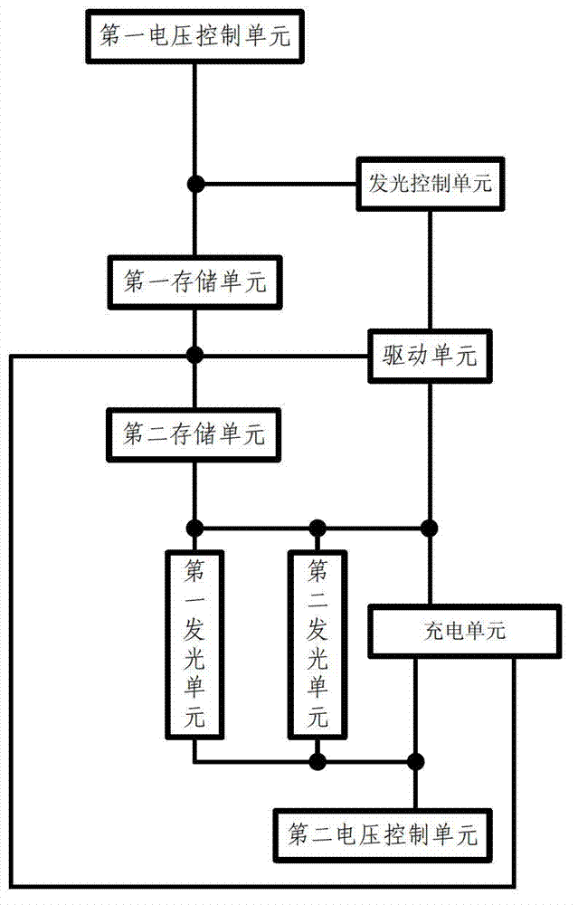
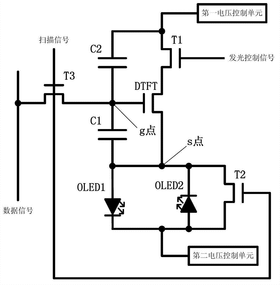
[0065] The circuit of the present invention such as figure 1 As shown, it includes: a light emitting control unit, a charging unit, a driving unit, a first storage unit, a second storage unit, a first light emitting unit, a second light emitting unit, a first voltage control unit and a second voltage control unit;

[0066] 1. A light-emitting control unit, the light-emitting control unit is respectively connected to the drive unit, the first storage unit and the first voltage control unit; it is used to control the light-emitting unit to emit light under the control of a light-emitting control signal;

[0067] The lighting control unit includes:

[0068] A first transistor, the gate of the first transistor is connected to the light-emitting control signal; the source of the first transistor is connected to the first voltage control unit; the drain of the first transistor is connected to the driving unit.

[0069] 2. The drive unit is respectively connected to the first storag...

Embodiment 2

[0100] The present invention also provides a display device, which includes the AC-driven OLED circuit described in Embodiment 1 above.

Embodiment 3

[0102] A driving method for AC driving an OLED circuit. The driving method will be described below by taking the structure of the driving circuit described in Embodiment 1 as an example.

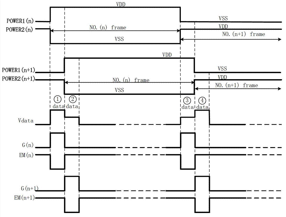
[0103] The method passes through the timing diagram corresponding to the actual circuit diagram of the present invention ( image 3 )Be explained. image 3 Among them, POWER1 is the voltage output waveform of the first voltage control unit; POWER2 is the voltage output waveform of the second voltage control unit; Vdata is the waveform of the data signal; G is the waveform of the scanning signal; EM is the waveform of the light control signal; n is nth frame. The corresponding operations are as follows:

[0104] Charging stage of the first storage unit. Charging the first storage unit (first capacitor C1);

[0105] controlling the scanning signal to be at a high potential; controlling the light emitting control signal to be at a low potential;

[0106] The charging unit is turned on, and ...


PUM


Abstract

Disclosed are an OLED alternating-current drive circuit, drive method and display device in the technical field of display.The present invention comprises a light-emitting control unit, a charging unit, a drive unit, a first storage unit, a second storage unit, a first light-emitting unit, a second light-emitting unit, a first voltage control unit and a second voltage control unit.In the present invention, both the first light-emitting unit and the second light-emitting unit which are reversely connected are used, to enable the first light-emitting unit and the second light-emitting unit to alternately emit light within two adjacent frame time periods, only one light-emitting unit to emit light for display and the other light-emitting unit to be in reverse bias within the same frame time period, and when the next frame arrives, the two to alternate;alternating-current drive of the light-emitting units is realized, and the utilization efficiency of energy is increased;the incentive causing the light-emitting units to age is thoroughly eliminated, the life of the light-emitting units is greatly prolonged, the influence of line internal resistance on the light-emitting current is eliminated, and the picture display quality is improved.

Description

technical field [0001] The invention relates to the field of display technology, in particular to an AC driving OLED circuit, a driving method and a display device. Background technique [0002] OLED is driven to emit light by the current generated by the driving transistor in saturation state. At present, OLED is facing many problems, the most important of which are: [0003] 1. Low-temperature polysilicon (LTPS) technology, the mainstream driving technology of organic light-emitting diodes (OLEDs), has a transistor threshold voltage of V th The uniformity of the gray scale is very poor, so that when the same gray scale voltage is input, different threshold voltages will generate different driving currents, resulting in inconsistency of the current. In addition to the circuit for low-temperature polysilicon (LTPS) process on transistor threshold voltage V th In addition to compensating for the difference, improving the process is also a solution. For example, the oxide t...

Claims


Application Information

Patent Timeline
Patent Type & Authority Patents(China)
IPC IPC(8): G09G3/32
CPCG09G3/3233G09G2300/0426G09G2300/0443G09G2300/0852G09G2310/0254G09G2310/0272G09G2310/0291G09G2320/043G09G2330/021
Inventor 青海刚祁小敬
Owner BOE TECH GRP CO LTD
Why Eureka
Try Eureka