Alternating current drive OLED (Organic Light Emitting Diode) circuit, driving method and display device
An AC drive and circuit technology, used in static indicators, instruments, etc., can solve problems such as uneven display and OLED aging, and achieve the effect of improving compound efficiency, prolonging service life, and being easy to mass production and application.
- Summary
- Abstract
- Description
- Claims
- Application Information
AI Technical Summary
Problems solved by technology
Method used
Image
Examples
Embodiment 1
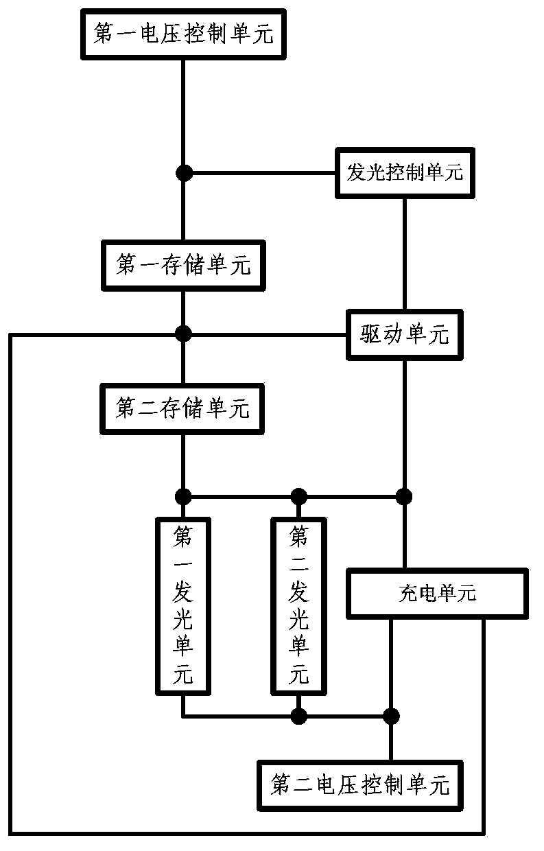
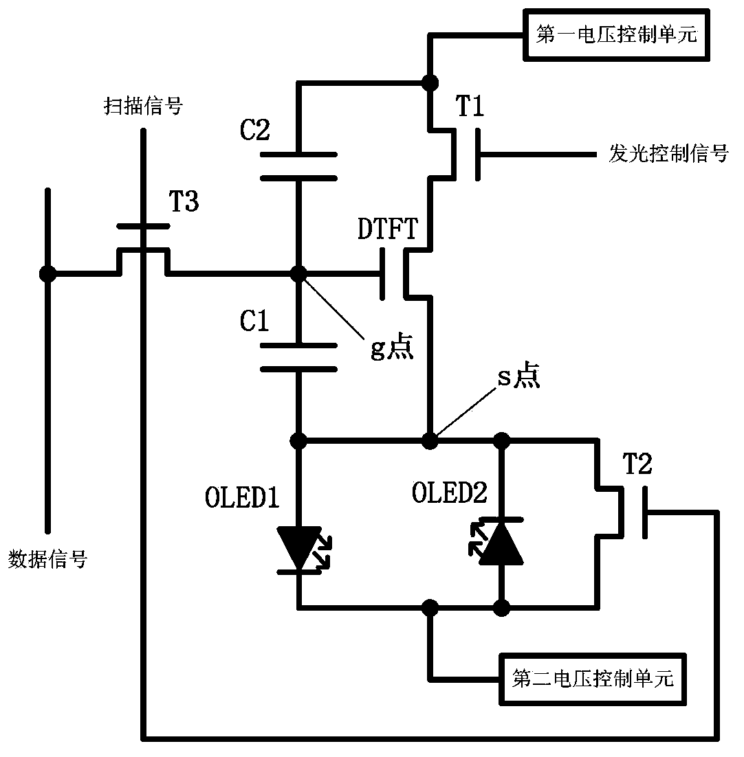
[0065] The circuit of the present invention such as figure 1 As shown, it includes: a light emitting control unit, a charging unit, a driving unit, a first storage unit, a second storage unit, a first light emitting unit, a second light emitting unit, a first voltage control unit and a second voltage control unit;
[0066] 1. A light-emitting control unit, the light-emitting control unit is respectively connected to the drive unit, the first storage unit and the first voltage control unit; it is used to control the light-emitting unit to emit light under the control of a light-emitting control signal;
[0067] The lighting control unit includes:
[0068] A first transistor, the gate of the first transistor is connected to the light-emitting control signal; the source of the first transistor is connected to the first voltage control unit; the drain of the first transistor is connected to the driving unit.
[0069] 2. The drive unit is respectively connected to the first storag...
Embodiment 2
[0100] The present invention also provides a display device, which includes the AC-driven OLED circuit described in Embodiment 1 above.
Embodiment 3
[0102] A driving method for AC driving an OLED circuit. The driving method will be described below by taking the structure of the driving circuit described in Embodiment 1 as an example.
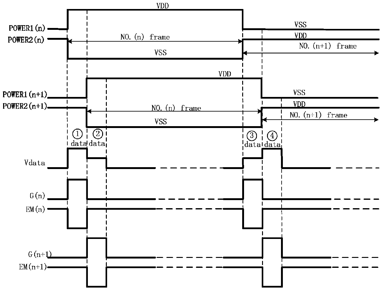
[0103] The method passes through the timing diagram corresponding to the actual circuit diagram of the present invention ( image 3 )Be explained. image 3 Among them, POWER1 is the voltage output waveform of the first voltage control unit; POWER2 is the voltage output waveform of the second voltage control unit; Vdata is the waveform of the data signal; G is the waveform of the scanning signal; EM is the waveform of the light control signal; n is nth frame. The corresponding operations are as follows:
[0104] Charging stage of the first storage unit. Charging the first storage unit (first capacitor C1);
[0105] controlling the scanning signal to be at a high potential; controlling the light emitting control signal to be at a low potential;
[0106] The charging unit is turned on, and ...
PUM
 Abstract
Description
Claims
Application Information
 - R&D
- Intellectual Property
- Life Sciences
- Materials
- Tech Scout
- Unparalleled Data Quality
- Higher Quality Content
- 60% Fewer Hallucinations
Browse by: Latest US Patents, China's latest patents, Technical Efficacy Thesaurus, Application Domain, Technology Topic, Popular Technical Reports.
© 2025 PatSnap. All rights reserved.Legal|Privacy policy|Modern Slavery Act Transparency Statement|Sitemap|About US| Contact US: help@patsnap.com


