Video display device

a technology of video display and display screen, applied in the field of video display device, can solve the problems of flickering artifacts, eye strain, negatively affecting the observer, etc., and achieve the effects of reducing motion trailing and disruptive flickering, and reducing motion trailing

Inactive Publication Date: 2007-06-07
SHARP KK
View PDF3 Cites 147 Cited by
  • Summary
  • Abstract
  • Description
  • Claims
  • Application Information

AI Technical Summary

Benefits of technology

[0033] Clearly from FIGS. 117 and 118, there is a tradeoff between the amount of trailing and the amount of flickering in relation to the duty ratio. It is impossible to simultaneously reduce motion trailing and disruptive flickering. However, if the curve is moved as indicated by the white arrow in FIG...

Problems solved by technology

However, the impulse-type display above results in artifacts called flickering.
The disruptive flickering causes eye strain and otherwise negatively affects the o...

Method used


Image

  • Video display device
  • Video display device
  • Video display device

Examples


embodiment 1

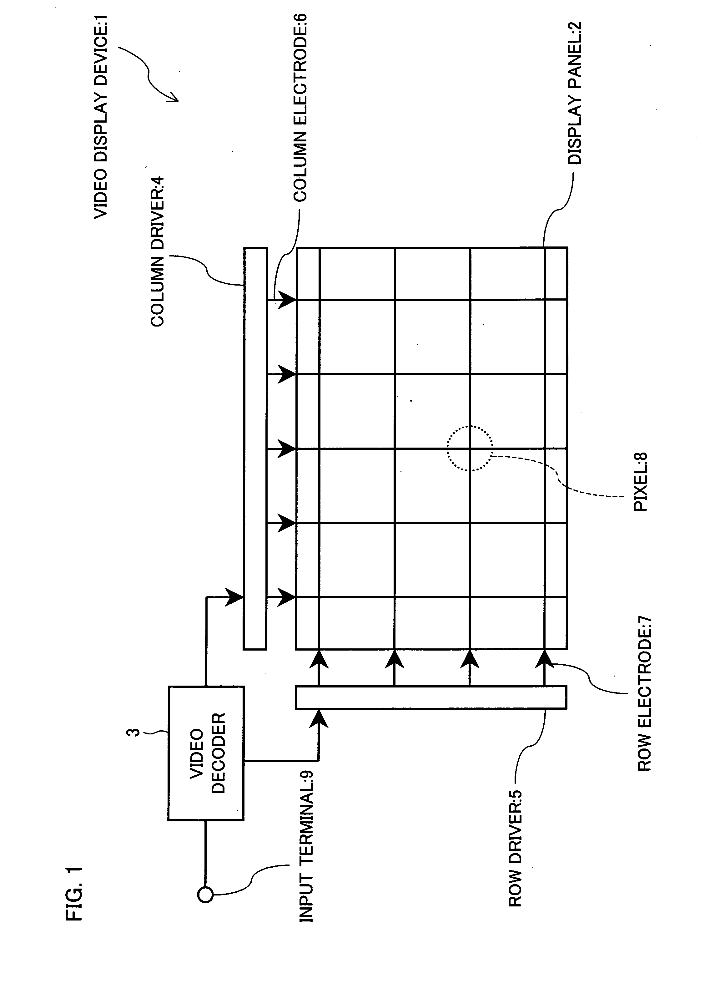
[0174]FIG. 1 is an illustration of the configuration of a video display device 1 in accordance with an embodiment of the present invention. As shown in FIG. 1, the video display device 1 include a display panel (video display means) 2, a video decoder 3, column driver 4, a row driver 5, column electrodes 6, row electrodes 7, and an input terminal 9.

[0175] The input terminal 9 receives a video signal, for example, an NTSC video signal. The video decoder 3 performs demodulation on the incoming video signal. The decoder 3 outputs video data to the column driver 4 and a synchronization signal to the row driver 5.

[0176] The column driver 4 supplies the video data to the plurality of column electrodes 6. The row driver 5 sequentially selects the plurality of row electrodes 7 in accordance with the synchronization signal. Supposing a 1 / 60 second cycle for the synchronization signal and 525 row electrodes, for example, a row electrode is selected for 32 microseconds (= 1 / 60 / 525).
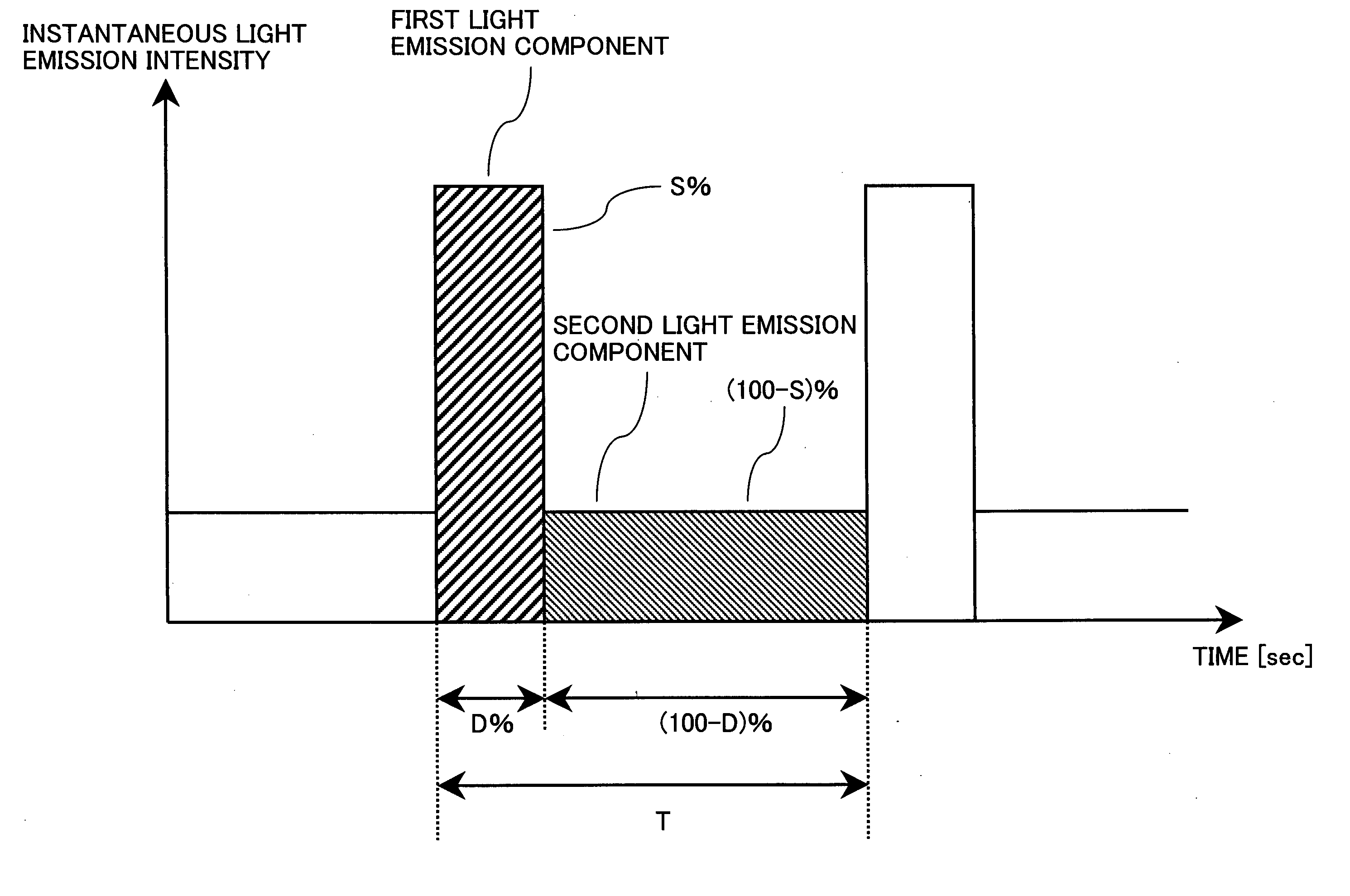
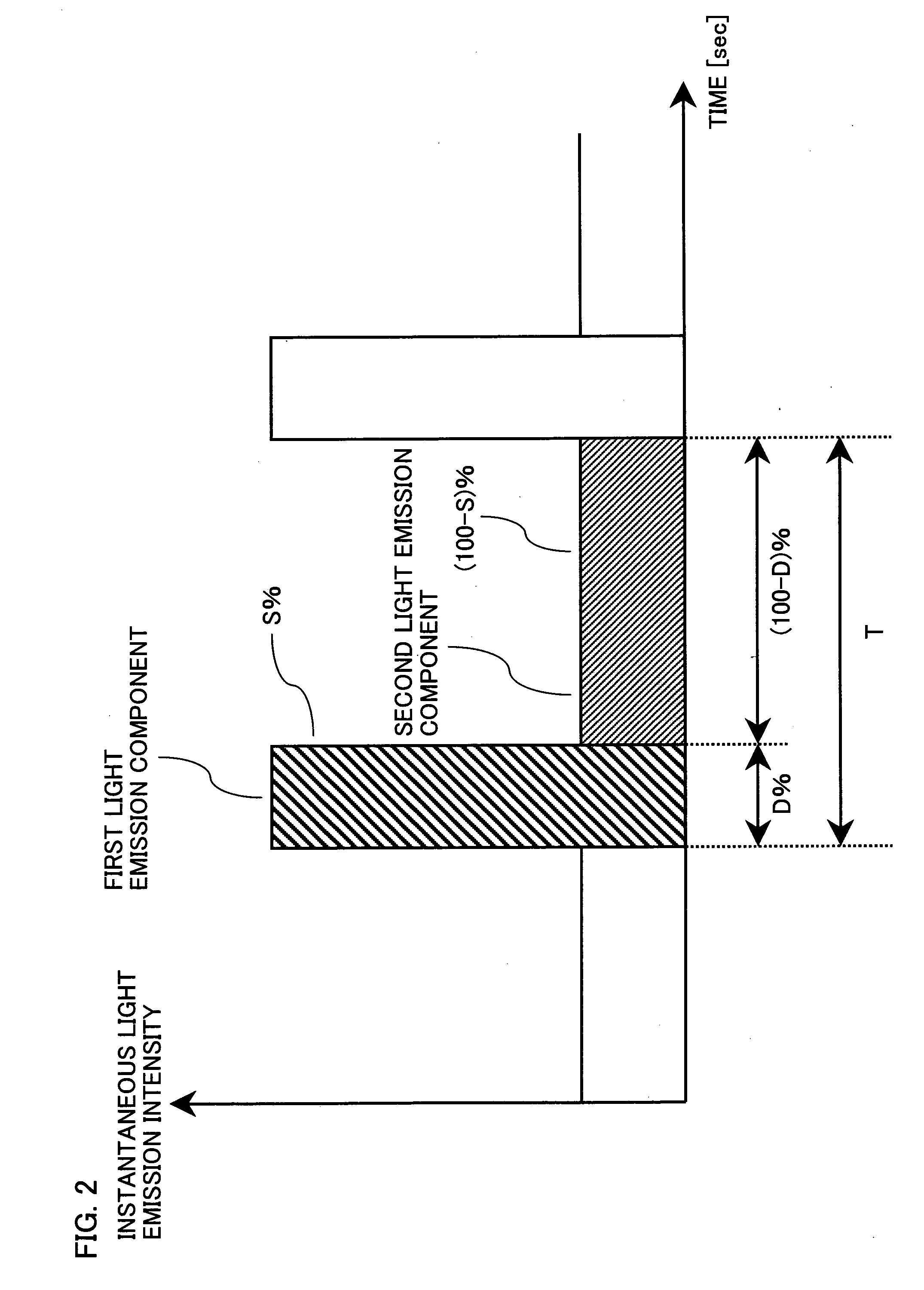
[0177] A...

embodiment 2

[0261] A video display device in accordance with another embodiment of the present invention will be described in reference to FIGS. 25 to 31. FIG. 25 is a cross-sectional view of a video display device in accordance with the present embodiment. Referring to FIG. 25, a video display 10 of the present embodiment contains a light source (light source body) 11, a display panel (video display means) 12, a diffusion plate 13, and a chassis 14. Pixels (not shown) are defined on the display panel 12.

[0262] Inside the video display 10 configured as above, a space is provided between the diffusion plate 13 and the chassis 14. The light source 11 is disposed in the lower part of the space. The light source 11 emits illumination light onto the bottom surface of the diffusion plate 13.

[0263] The display panel 12 is, for example, a transmissive liquid crystal panel which modulates the illumination light having passed through the diffusion plate 13 when it passes through the panel 12. The illum...

embodiment 3

[0291] The present embodiment will describe applications of the present invention where the display panel in the video display device is, for example, a self-luminous active matrix organic EL panel.

[0292] Each pixel 20 in the organic EL panel provided in the video display device of the present embodiment contains, as shown in FIG. 32, a selector TFT 21 for selecting the pixel, a capacitor 22, an EL element 23, an EL drive TFT 24 to supply electric current to the EL element 23, and a luminance switching TFT 25.

[0293] The capacitor 22, coupled to the drain of the selector TFT 21, is receives from an external power supply a voltage (or electric charge) corresponding to the video to be displayed in the selection period for the pixel. The drain of the selector TFT 21 is coupled to the gate of the EL drive TFT 24. In the non-selection period, a current determined by the voltage built up across the capacitor 22 flows across the source and drain of the EL drive TFT 24.

[0294] The drain of...


PUM


Abstract

A first light emission component is emitted which accounts for D % of the vertical cycle of a video signal in terms of duration and S % of the light emission intensity of a pixel over the vertical cycle. A second light emission component is emitted which accounts for (100−D)% of the vertical cycle in terms of duration and (100−S)% of the light emission intensity. Settings are made so that D and S meet a set of conditions A, 62≦S<100, 0<D<100, and D<S; or a set of conditions B, 48<S<62 and D≦(S−48)/0.23.

Description

TECHNICAL FIELD [0001] The present invention relates to video display devices, and particularly to methods for improving display quality of a video display device having hold-type electro-optical conversion properties, the typical example of which being a liquid crystal display device. BACKGROUND ART [0002] Display devices which have recently become very popular, of which a typical example is the LCD (liquid crystal display), have found a wide variety of applications including compact mobile terminals and large screen televisions. [0003] Active matrix LCDs and organic EL (electroluminescent) displays differ in electro-optical conversion properties from CRTs (cathode ray tubes). In principle, the former maintain a substantially constant light emission luminance of a display screen throughout one frame of video display. Such a light emission property is referred to as a hold type. [0004] Current challenges are the hold-type driving causing blurs, trailing and bleeding, which lead to i...

Claims


Application Information

Patent Timeline
IPC IPC(8): G09G5/10G09G3/32G09G3/34
CPCG09G3/3233G09G3/3258G09G3/342G09G2300/0819G09G2300/0842G09G2300/0852G09G2300/0861G09G2310/0221G09G2310/0251G09G2310/0262G09G2310/06G09G2310/061G09G2320/0247G09G2320/0261G09G2320/062G09G2360/16G09G3/36G02F1/133G09G3/20
Inventor ITOH, HIROSHISEO, MITSUYOSHI
Owner SHARP KK
Why Eureka
Try Eureka