
Illumination brightness and color control system and method therefor

a color control system and illumination technology, applied in the direction of electric variable regulation, process and machine control, instruments, etc., can solve the problems of complicated calibration, affecting the lighting quality of the diode lighting module, and unable to apply the color sequence technique, so as to reduce the cost of the control system

Active Publication Date: 2007-06-07
IND TECH RES INST
View PDF15 Cites 87 Cited by
  • Summary
  • Abstract
  • Description
  • Claims
  • Application Information

AI Technical Summary

Benefits of technology

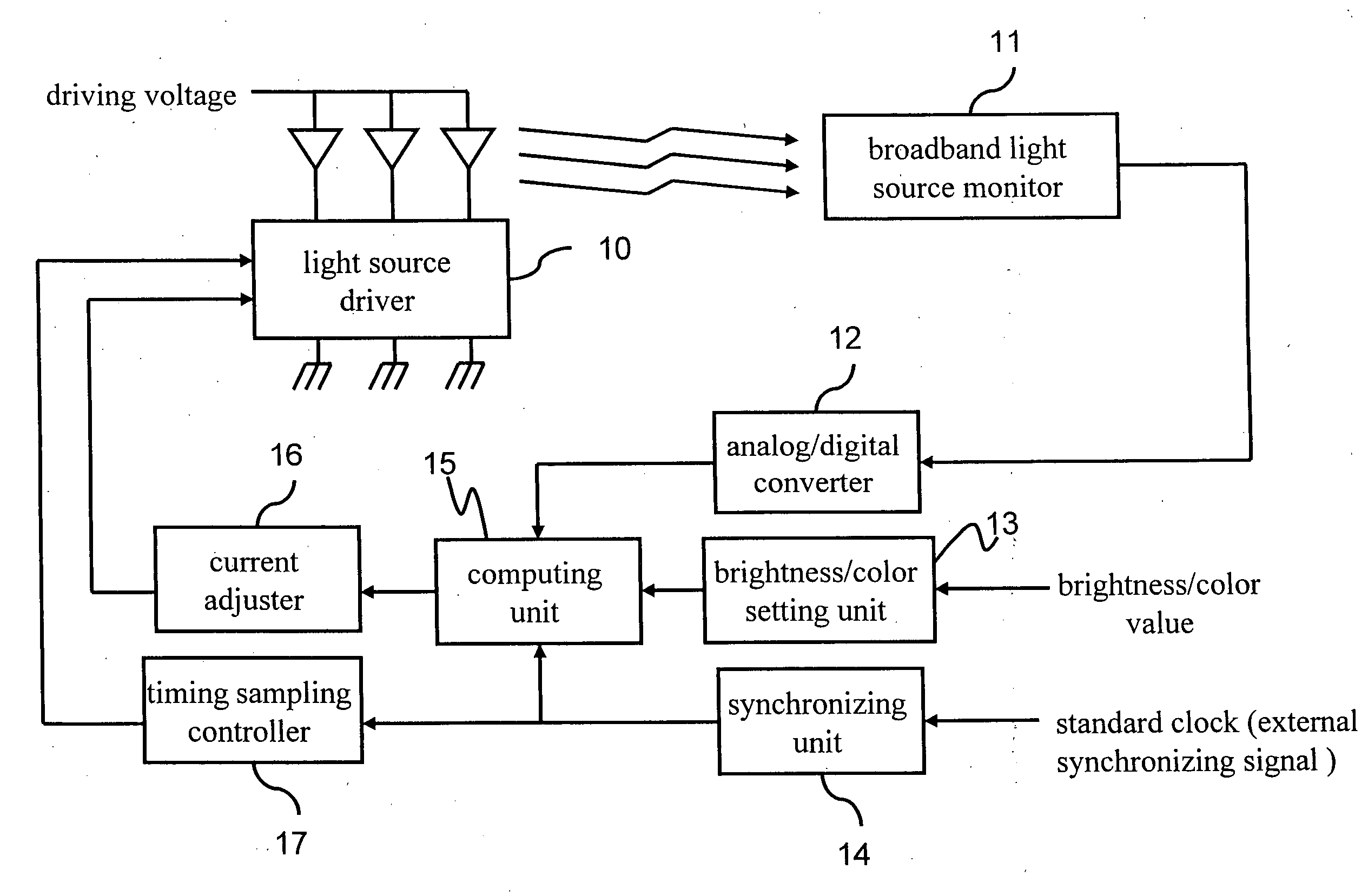
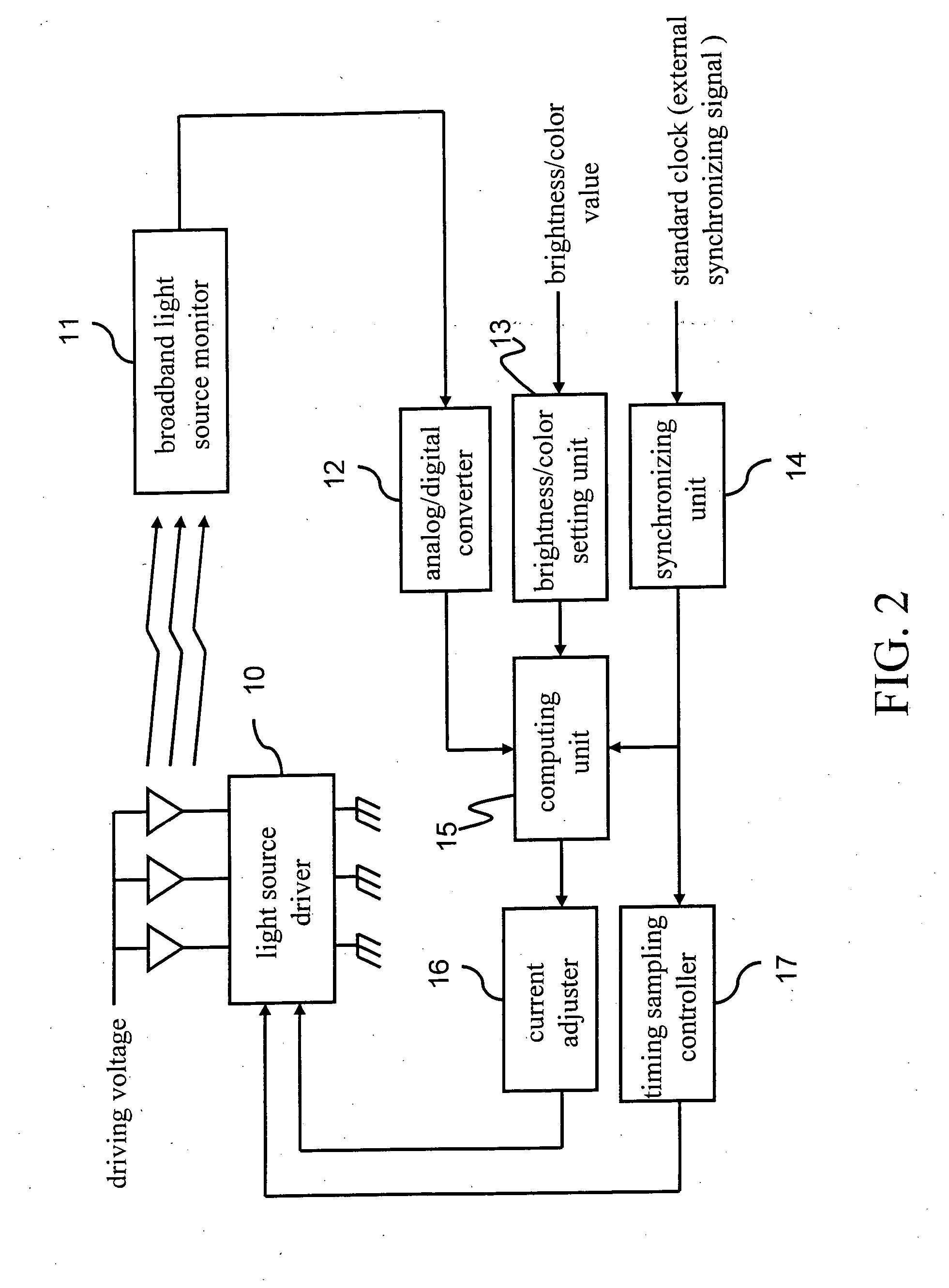
[0009] In view of the above, the object of the present invention is to provide an illumination brightness and color control system and method therefor, wherein a single broadband sensor is used to sense and sample a point light source for the lighting emitting state in a time division manner, and to carry out feedback control so as to adjust the illumination brightness of the point light source, thereby reducing the cost of the control system.
[0014] According to the illumination brightness and color control system and method therefor, a single broadband photosensor is used to respectively sense and sample the diodes in each wavelength for the luminous intensity signal values in a time division manner. Then, the luminous intensity signal value is computed with the target brightness / color value, for feedback controlling the illumination brightness of the point light source. The advantage for using a single broadband photosensor is that, the calibration process is easy and simple, and the manufacturing cost of the illumination brightness and color control system also can be reduced.

Problems solved by technology

However, the problem of unsteady brightness caused by temperature, aging, etc., affects the lighting quality of the diode lighting module.
Multiple groups of three-wavelength sensors are used in this method to read the luminous intensity and color components, such that it is relatively complicated in calibration, and it cannot be applied to the color sequence technique.
However, the multi-wavelength monitor used in this method must cooperate with several photosensors in different wavelengths, such that it is still relatively complicated in calibration, with high cost, and it cannot be applied to the color sequence technique.

Method used


Image

  • Illumination brightness and color control system and method therefor
  • Illumination brightness and color control system and method therefor
  • Illumination brightness and color control system and method therefor

Examples


Embodiment Construction

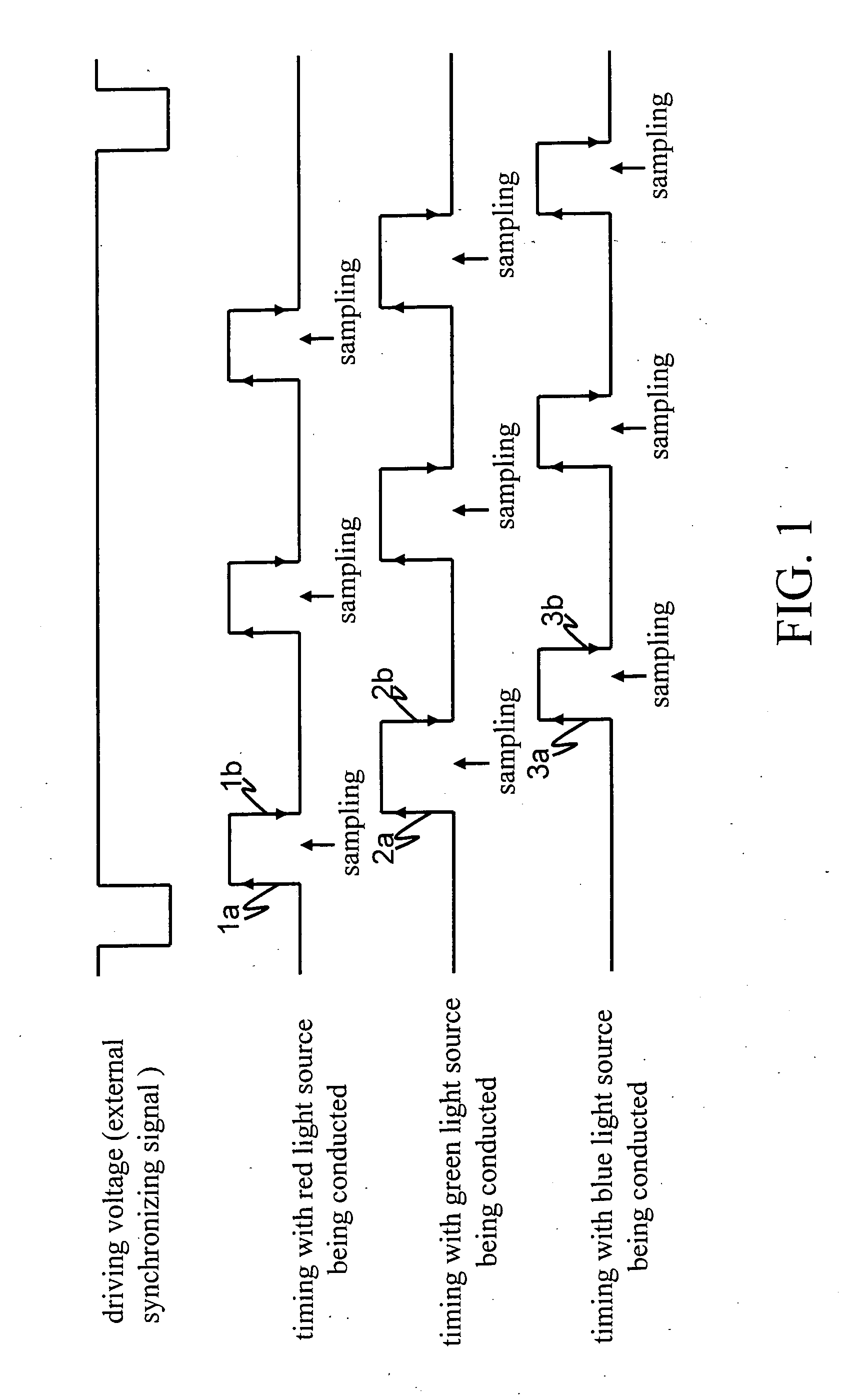
[0022] Referring to FIG. 1, it is a schematic view of the sampling timing of the light signal according to an embodiment of the present invention, wherein the point light source can be implemented by a multi-wavelength diode, and the conducting time for the diodes in each wavelength varies depending on the different luminous efficiency of each diode. First, a first rising trigger signal 1a is generated, for driving the red light diode (not shown) to be conducted for a predetermined time period; the sensing and sampling are carried out when the red light diode has been conducted, for acquiring the luminous intensity signal value generated by the red light diode.

[0023] Then, a first falling trigger signal 1b is generated, for turning off the red light diode; meanwhile, a second rising trigger signal 2a is generated, for driving a green light diode (not shown) to be conducted for a predetermined time period; and the sensing and sampling are carried out when the green light diode has b...


PUM


Abstract

An illumination brightness and color control system and method therefor are provided, implemented in a time division manner. A single photosensor senses and samples a point light source for the luminous intensity signal value. Then, the luminous intensity signal value at each wavelength and a target brightness / color value are computed to acquire a corrected current value, and the corrected current value is fed back to a light source driver. Therefore, the brightness / color value of the diode is adjusted to be in a steady state.

Description

CROSS-REFERENCE TO RELATED APPLICATIONS [0001] This non-provisional application claims priority under 35 U.S.C. § 119(a) on Patent Application No(s). 094143235 filed in Taiwan, R.O.C. on Dec. 7, 2005 the entire contents of which are hereby incorporated by reference. BACKGROUND OF THE INVENTION [0002] 1. Field of Invention [0003] The present invention relates to a brightness and color control system and method therefor, and more particularly to a brightness and color control system of a point light source (for example, a multi-wavelength diode light source) and method therefor. [0004] 2. Related Art [0005] The currently used diode lighting module as light source adds greater value to liquid crystal panels due to the advantages of high luminance, mercury free, high color reproducibility, and high resolution refinement, etc., such that the applications of the diode lighting module go beyond the field of portable electronic product and quickly extend to other fields, such as transportat...

Claims


Application Information

Patent Timeline
Patent Type & Authority Applications(United States)
IPC IPC(8): G09G3/14H01L33/00H05B37/02
CPCG09G3/3413G09G2320/0242G09G2320/041G09G2320/043G09G2320/0633G09G2360/145H05B33/0869Y02B20/341H05B45/22Y02B20/30
Inventor HUANG, JUI-FENGLU, CHUN-TE
Owner IND TECH RES INST
Learn More