Vehicle control system and automobile using the same

a control system and vehicle technology, applied in the field of control systems, can solve the problems of increasing the calorific value of the electronic control unit b>1/b>′, increasing the manufacturing cost and the cost of the whole vehicle control system in its turn, and reducing the cost of the control system

Inactive Publication Date: 2006-02-14
HITACHI LTD
View PDF5 Cites 1 Cited by
  • Summary
  • Abstract
  • Description
  • Claims
  • Application Information

AI Technical Summary

Benefits of technology

[0013]The present invention is made to solve the above problems and its object is to provide a vehicle control system for reducing the cost of the control system by dispersing actuator drivers and controlling the heat produced in an electronic control unit, making the actuator drivers independent and keeping the reliability and functionality of the control system even after dispersing the actuator drivers and provide a car using the system.
[0015]In the case of the vehicle control system of the present invention constituted as described above, the actuator drivers are set to the actuator side separately from the electronic control unit and dispersed correspondingly to the actuators one-to-one. Therefore, it is possible to reduce the cost of the control system by controlling the heat produced in the electronic control unit. Moreover, because each of the actuator drivers is made independent as a system, it is possible to keep the reliability and functionality of the control system even after dispersing the actuator drivers.

Problems solved by technology

Therefore, as shown by the conventional vehicle control system 60′ in FIG. 11, when the actuator driver 4′ is concentratedly set to one place in the electronic control unit 1′, a problem occurs that the calorific value of the whole of the electronic control unit 1′ is increased by the actuator driver 4′ serving as a heat-producing part and the increase of the calorific value may affect control.
Thus, a problem occurs that the manufacturing cost and the cost of the whole vehicle control system in its turn increase.
However, it is not sufficient to merely disperse the actuator drivers because the following are indispensable for a present engine control system: a self-diagnosis function for diagnosing a trouble such as a disconnection or short circuit of an actuator and communicating the diagnosed state to an arithmetic processing section of an electronic control unit, a self-protection function for preventing an actuator driver from being broken down due to overcurrent or overheat when the above trouble occurs, and a timer circuit when PWM(Pulse Width Modulation)-controlling the dispersed actuator in a multiplex communication system through a serial communication line.
In the case of the above prior art, however, the actuator drivers are not dispersed to each actuator side separately from the electronic control unit or the actuator drivers are not dispersed to easily radiate heat even if the drivers are set to the outside of the electronic control unit.
Moreover, the drivers are not independent drivers capable of constructing an actual system.
Therefore, it is not particularly considered to maintain the reliability and functionality of the control system even if reducing the radiation-component cost of the vehicle control system by reducing the heat produced in the electronic control unit and dispersing the actuator drivers.

Method used


Image

  • Vehicle control system and automobile using the same
  • Vehicle control system and automobile using the same
  • Vehicle control system and automobile using the same

Examples


first embodiment

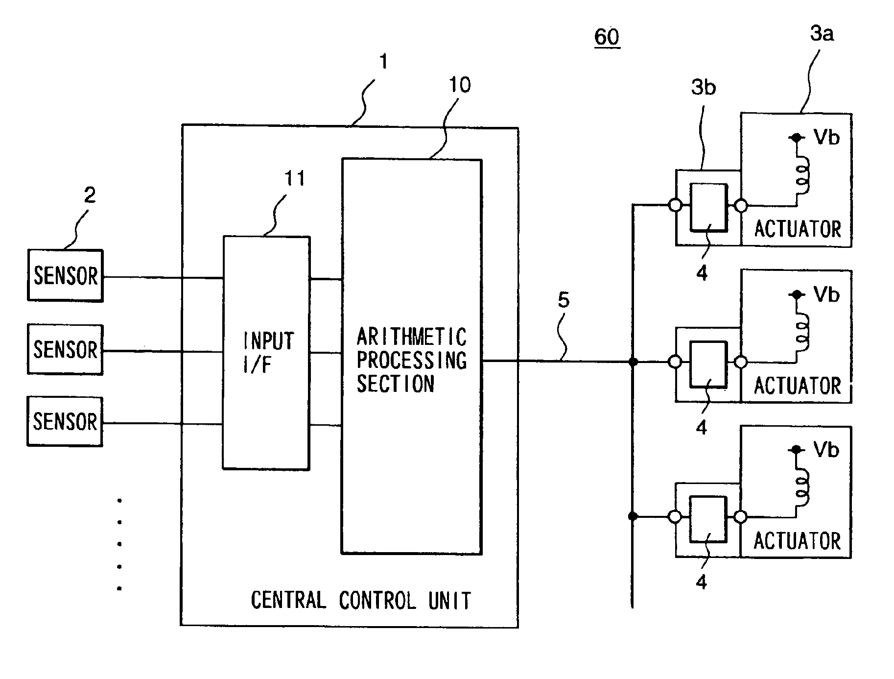
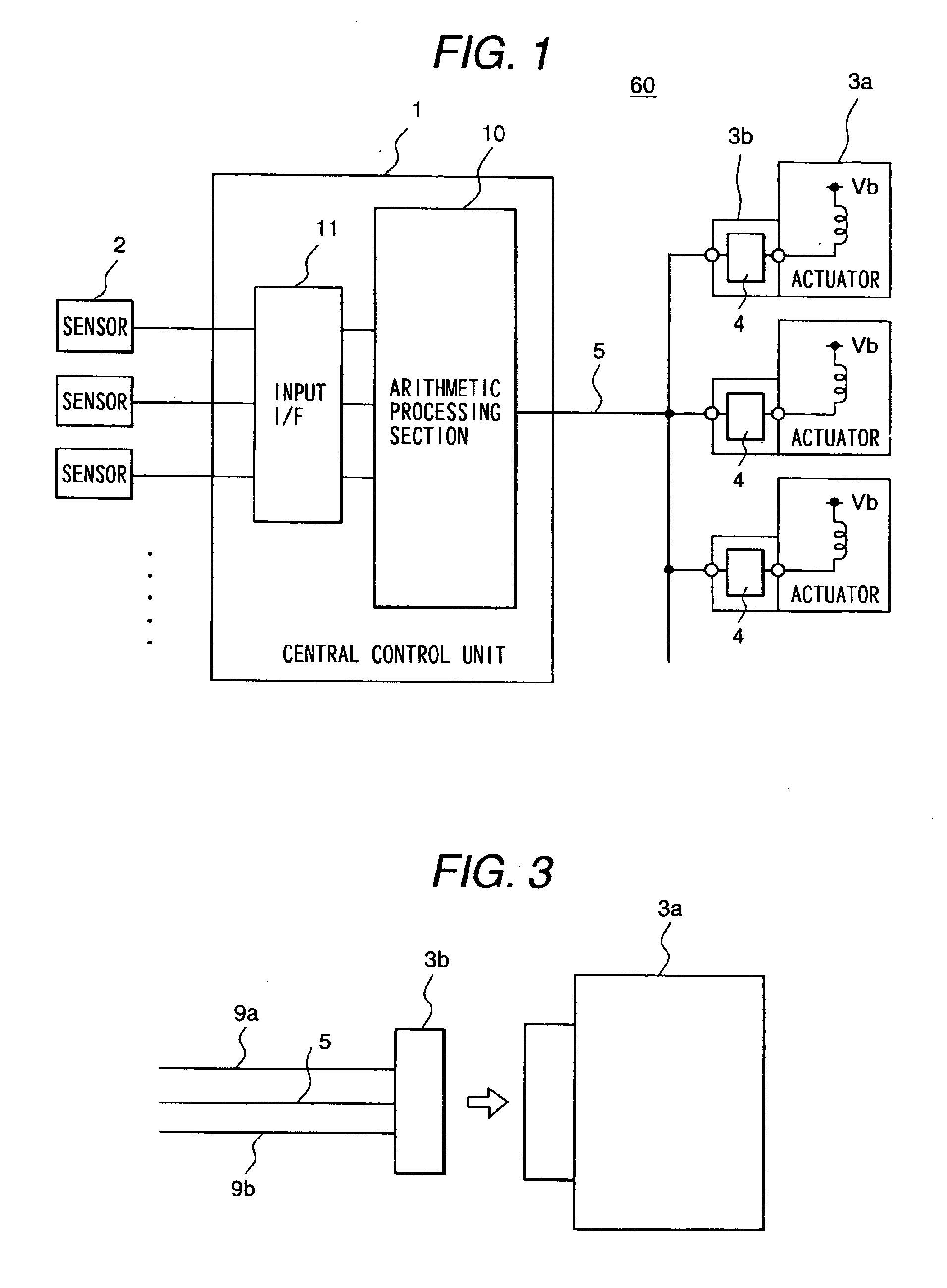
[0035]FIGS. 1 to 4 show the vehicle control system of the first embodiment, in which FIG. 1 shows a block diagram of the vehicle control system.

[0036]The vehicle control system 60 is constituted of an electronic control unit (ECU) 1, a plurality of sensors 2, a plurality of actuators 3a, and a plurality of actuator drivers 4, in which predetermined operations are performed by the electronic control unit in the engine room of a vehicle in accordance with signals of the sensors 2 set in the engine room to drive the actuators 3a serving as loads through the actuator drivers 4.

[0037]The electronic control unit 1 is constituted of an input interface (input I / F) 11 and an arithmetic processing section 10. The actuators 3a are driven by the actuator drivers 4 and the actuator drivers 4 are set to the actuator-3a side separately from the electronic control unit 1 and dispersed correspondingly to the actuators 3a.

[0038]The actuator drivers 4 are built in connectors 3b connected to the actua...

second embodiment

[0054]FIG. 5 shows a block diagram of the vehicle control system of the

[0055]The vehicle control system 60A has the same configuration as the vehicle control system 60 of the first embodiment except the configuration of signal lines between the arithmetic processing section 10 of an electronic control unit (ECU) 1A and actuator drivers 4A. Therefore, differences between the first and second embodiments are mainly described below.

[0056]The actuator drivers 4A of the vehicle control system 60A are set to the actuator-3a side separately from the electronic control unit 1A and dispersed in connectors 3b correspondingly to the actuators 3a. Moreover, the actuator drivers 4A respectively have a self-diagnosis section, a self-protection section, and a communication control section and made independent so as to make it possible to construct an actual system even if the drivers 4A are set to the outside of the electronic control unit 1A.

[0057]Then, the arithmetic processing section 10 of the...

third embodiment

[0058]FIGS. 6 and 7 show the vehicle control system of the third embodiment, in which FIG. 6 shows a block diagram of the vehicle control system.

[0059]Because the vehicle control system 60B has the same configuration as those of the vehicle control systems of the first and second embodiments except the configuration of transceiving signals between the arithmetic processing unit 10 of an electronic control unit (ECU) 1B and actuator drivers 4B, difference points between the third embodiment on one hand and the first and second embodiments on the other are mainly described below.

[0060]The actuator drivers 4B of the vehicle control system 60 are set to the actuator-3a side separately from the electronic control unit 1B and dispersed in connectors 3b correspondingly to the actuators 3a. Moreover, the actuator drivers 4B respectively have a self-diagnosis section, a self-protection section, a timer section, a radio communication control section, and an antenna and are made independent so...


PUM


Abstract

A low-cost vehicle control system and a car using the system controls radiation of an actuator driver and thereby reduces the radiation component cost and allows downsizing of an electronic control unit to improve the versatility. The vehicle control system has an electronic control unit, a plurality of actuators and actuator drivers for driving the actuators at the actuator side. The actuator drivers, respectively, have a independent self-diagnosis section, a self-protection section, and a communication control section and are dispersed correspondingly to the actuators.

Description

[0001]This application is a divisional of application Ser. No. 09 / 801,656, filed Mar. 9, 2001, now U.S. Pat. No. 6,625,522.BACKGROUND OF THE INVENTION[0002]The present invention relates to a control system of a vehicle such as a car and an automobile using the same, particularly to a vehicle control system capable of reducing the cost of the control system and an automobile using the same.[0003]FIG. 11 is a block diagram of a conventional vehicle control system of a car or the like.[0004]The vehicle control system 60′ is constituted of an electronic control unit (ECU) 1′, a plurality of sensors 2′, and a plurality of actuators 3a′, in which a predetermined operation is performed by the electronic control unit 1′ set in a cabin in accordance with signals of the sensors 2′ provided in the engine room of the vehicle to drive the actuators 3a′. [0005]The electronic control unit 1′ is constituted of an input interface (input I / F) 11′, an arithmetic processing section 10′, and an actuator...

Claims


Application Information

Patent Timeline
Patent Type & Authority Patents(United States)
IPC IPC(8): G06F7/00B60R16/02B60W50/00F02D41/30G06F17/00H04Q9/00
CPCB60T8/885B60T2270/406B60W50/00B60W50/0205F02D41/22F02D41/266F02D41/3005F02D2400/18B60W2050/0006
Inventor SAKURAI, KOHEIKANEKAWA, NOBUYASUMURABAYASHI, FUMIOWATABE, MITSURUHAYASHIBARA, TOSHIO
Owner HITACHI LTD
Why Eureka
Try Eureka