Connection equipment and a field device control system

a control system and equipment technology, applied in the direction of program control, instruments, electric digital data processing, etc., can solve the problems of time-consuming and more prone to errors, and achieve the effect of reducing wiring costs and increasing the space available for the engineer or operator working in the control room

Active Publication Date: 2017-10-24
YOKOGAWA ELECTRIC CORP
View PDF13 Cites 1 Cited by
  • Summary
  • Abstract
  • Description
  • Claims
  • Application Information

AI Technical Summary

Benefits of technology

[0023]There are advantages in the Fieldbus system above. As the control system 105 performs marshaling, the wiring cost is reduced. And as the physical marshaling board can be omitted, the space available for the control room engineer or operator for working in the control room is increased.
[0031]The present invention is invented considering the problems above. The purpose of this invention is to provide the connection equipment and the field device control system, which can reduce the overall field device control system cost, can omit the marshaling board, does not require the engineer in the control room or in the field to check, perform, or be in charge of marshaling of the terminal port and the field device, can increase the space available for the control room engineer or operator in the control room, and can limit the influence of electrical short circuit to a certain scope.

Problems solved by technology

However, there is a problem that an engineer or operator in the control room has to be in charge of the software which performs marshaling i.e. check and control the relationship between the field device 101 and the terminal port in JB 100.
This is time consuming and more prone to error due to possible miscommunication.

Method used


Image

  • Connection equipment and a field device control system
  • Connection equipment and a field device control system
  • Connection equipment and a field device control system

Examples


first embodiment

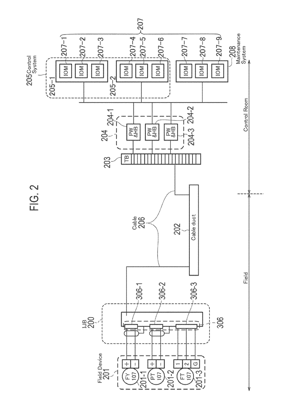
[0049]A connection equipment (IJB: Isolated Junction Box) 200 and a field device control system according to the first embodiment of this invention is explained referring to the figures.

[0050](Overall Configuration of the Field Device Control System)

[0051]The field device control system according to this embodiment is shown in FIG. 2. As it is shown in FIG. 2, the field device control system according to this embodiment comprises one or more field devices 201, IJB 200, a cable duct 202, a terminal board (TB) 203, Power and Hub unit (PW&HB unit) 204, control systems (205), a maintenance system 208 and one or more input and output modules (IOM) 207.

[0052]In the field device control system according to this embodiment, the control system 205 is configured to control the one or more field devices 201 via IJB 200, which is connected to the control system 205 by a cable 206, and to provide IJB 200 with an electric power signal via the cable 206.

[0053]The one or more field devices 201 are ...

second embodiment

[0152]The second embodiment according to the present invention is explaining referring to FIG. 9 to FIG. 12. It should be noted that the difference from the first embodiment is mainly explained, and the explanation which is the same as the first embodiment is omitted for purposes of clarity alone, and not as a limitation.

[0153](Overall Configuration of the Field Device Control System)

[0154]The field device control system according to this embodiment is shown in FIG. 9. The field device control system according to this embodiment has a security control unit 600. The security control unit 600 is placed between the control system 205 and IJB 200. The security control unit 600 may be placed between the control system 205 and the PW&HB unit 204 or between the PW&HB unit 204 and the cable duct 202. The security control unit 600 is connected to IJB 200 and to the control system 205 via the cable 206.

[0155]The security control unit 600 checks the communication signal and / or the electric pow...


PUM


Abstract

A connection equipment (IJB 200) for connected to a control system (205) via a cable (206) and a field device (201) via a terminal port (306), comprising: a processor (300) configured to determine the terminal port corresponding to the field device reference included in a communication signal received from the control system and to instruct a transmitter / receiver (304) to transmit the communication signal to the terminal port determined, and an isolator (305B) configured to electrically isolate the communication signal to be transmitted to the field device via the terminal port and the electric power signal to be provided to the field device via the terminal port, from the other terminal ports.

Description

TECHNICAL FIELD[0001]The present invention relates to a connection equipment connected to a field device via a terminal port and to a control system, and, a field device control system for controlling a field device from a control system via a connection equipment.BACKGROUND ART[0002]In order to achieve an advanced automatic operation in a plant, etc., a field device control system, which comprises a field device (e.g. a measuring device, operation device), a control system for managing and controlling the field device (Control System), and the connection equipment (e.g. Junction Box) connected to the field device and the control system, have been configured conventionally.[0003]In a process plant, field devices such as sensors and actuators measure or drive processes such as fluid process performed by plant equipment. Examples of sensors are flowmeter, temperature indicator, and example of actuators is valves.[0004]Field devices are used in industries to control operation of a proc...

Claims


Application Information

Patent Timeline
Patent Type & Authority Patents(United States)
IPC IPC(8): G06F13/38G06F13/42G05B19/042
CPCG06F13/387G05B19/0423G06F13/426G05B2219/34421G05B2219/25139G05B2219/25462
Inventor SAKAMOTO, HIDEYUKI
Owner YOKOGAWA ELECTRIC CORP
Why Eureka
Try Eureka