Electric connection box

a technology of electric connection box and connection box, which is applied in the direction of printed circuit, electric/fluid circuit, vehicle components, etc., can solve the problems of inability to easily make free connections between the lower and upper cases, and inability to connect in the transverse direction, so as to reduce the cost of wire harnesses, enhance the efficiency of wiring operation, and improve the efficiency of wire harness layout

Active Publication Date: 2007-07-31
YAZAKI CORP
View PDF15 Cites 17 Cited by
  • Summary
  • Abstract
  • Description
  • Claims
  • Application Information

AI Technical Summary

Benefits of technology

[0010]This invention has been made in view of the above circumstances, and an object of the invention is to provide an electric connection box in which the efficiency of layout of wire harnesses is enhanced by inserting connectors from both of upper and lower sides, thereby reducing the cost of the wire harnesses, and also circuits can be freely changed by changing a wiring layout.
[0012]In the invention of the above Paragraph 1), the first cover is disposed at the upper side, and the second cover is disposed at the lower side, and therefore a plurality of connectors, connected to a plurality of circuits, can be inserted from the upper and lower sides. The connecting wire is electrically connected to the press-contacting terminals (inserted in the first wiring board) on the first wiring board, and is also electrically connected to the press-contacting terminals (inserted in the second wiring board) on the second wiring board. At this time, the connecting wire is arranged to be connected to the first wiring board and the second wiring board, and when the first and second wiring boards are stacked together, the connecting wire, extending over the first and second wiring boards, electrically connects the upper first wiring board-side press-contacting terminals and the lower second wiring board-side press-contacting terminals together. And besides, the connecting wire are selectively connected to the first wiring board-side press-contacting terminals and the second wiring board-side press-contacting terminals, and therefore can connect the plurality of circuits via the first and second wiring board-side press-contacting terminals on the first and second wiring boards. Therefore, by inserting the connectors from both of the upper and lower sides, the efficiency of layout of wire harnesses is enhanced, and the cost of the wire harnesses can be reduced, and the circuits can be freely changed by changing the wiring layout.
[0014]In the invention of the above Paragraph 2), the plurality of electric connection boxes can be combined together by the use of the interconnecting device, and therefore many circuits can be connected. And besides, when the wiring operation is to be effected, the plurality of electric connection boxes are separated from each other, and the wiring operation can be effected for each single electric connection box, and therefore it is not necessary to effect the cumbersome operation in the combined condition of the electric connection boxes, so that the efficiency of the wiring operation can be enhanced.
[0015]In the electric connection box of the present invention, there are achieved advantage that the efficiency of layout of wire harnesses is enhanced by inserting the connectors from both of the upper and lower sides, thereby reducing the cost of the wire harnesses and that the circuits can be freely changed by changing the wiring layout.

Problems solved by technology

However, in the above JP-A-2001-320814, connectors can be mounted only on the upper case, and therefore many circuits can not be connected to the electric connection box.
In the above JP-A-2000-188814, the connectors can be mounted on both of the lower and upper cases, but free connection can not be easily made between the lower and upper cases since an insulating plate is disposed between the upper and lower terminals.
In the above JP-A-2000-139016, the bus bars are arranged in the longitudinal direction, and therefore connection in the transverse direction is limited, and in the case where the electric connection box is small in size, more circuits and joints can not be absorbed.

Method used


Image

  • Electric connection box
  • Electric connection box
  • Electric connection box

Examples


Embodiment Construction

[0023]A preferred embodiment of the present invention will now be described in detail with reference to the drawings.

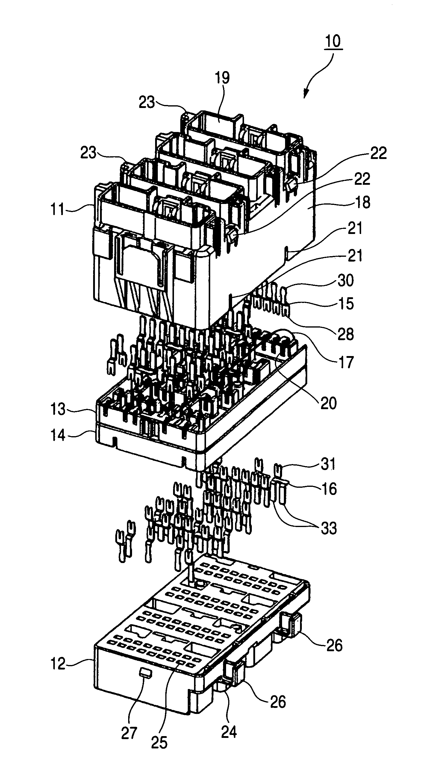
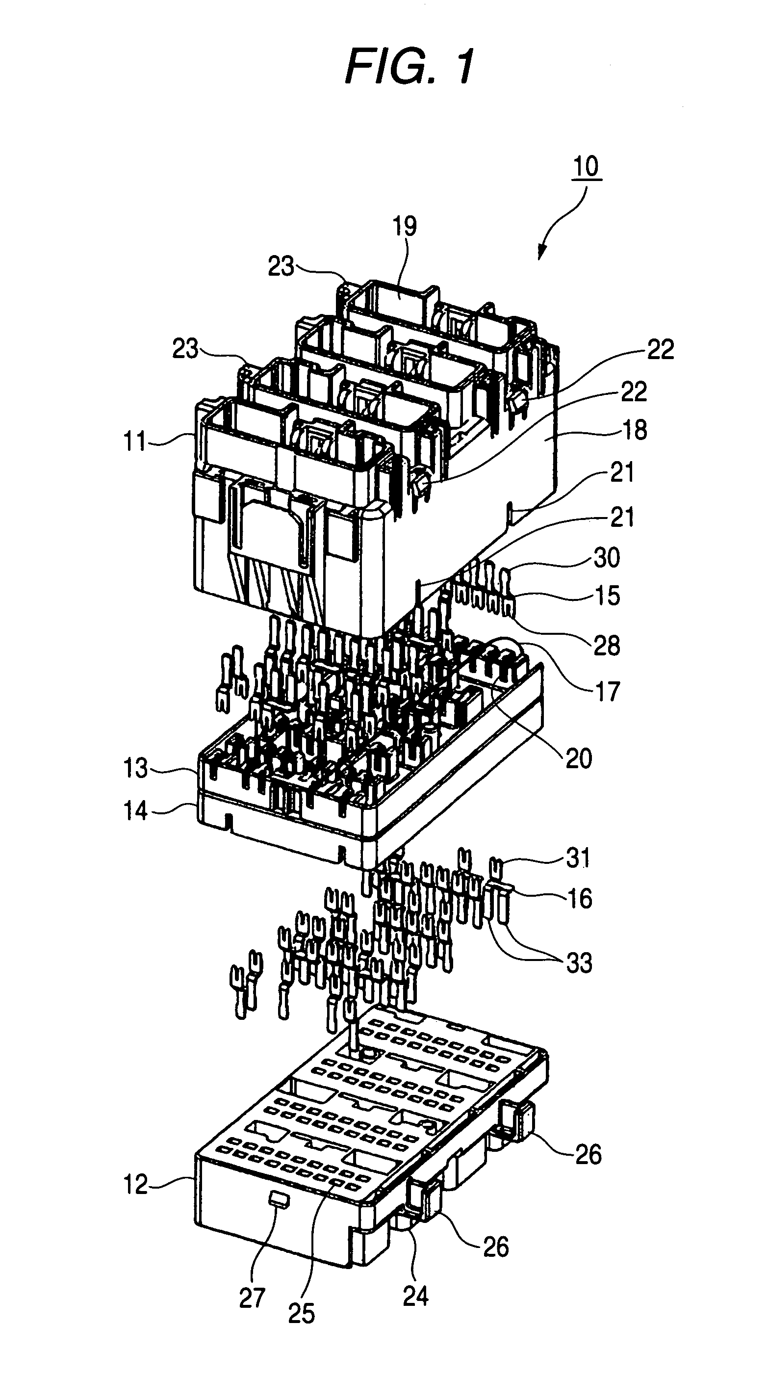
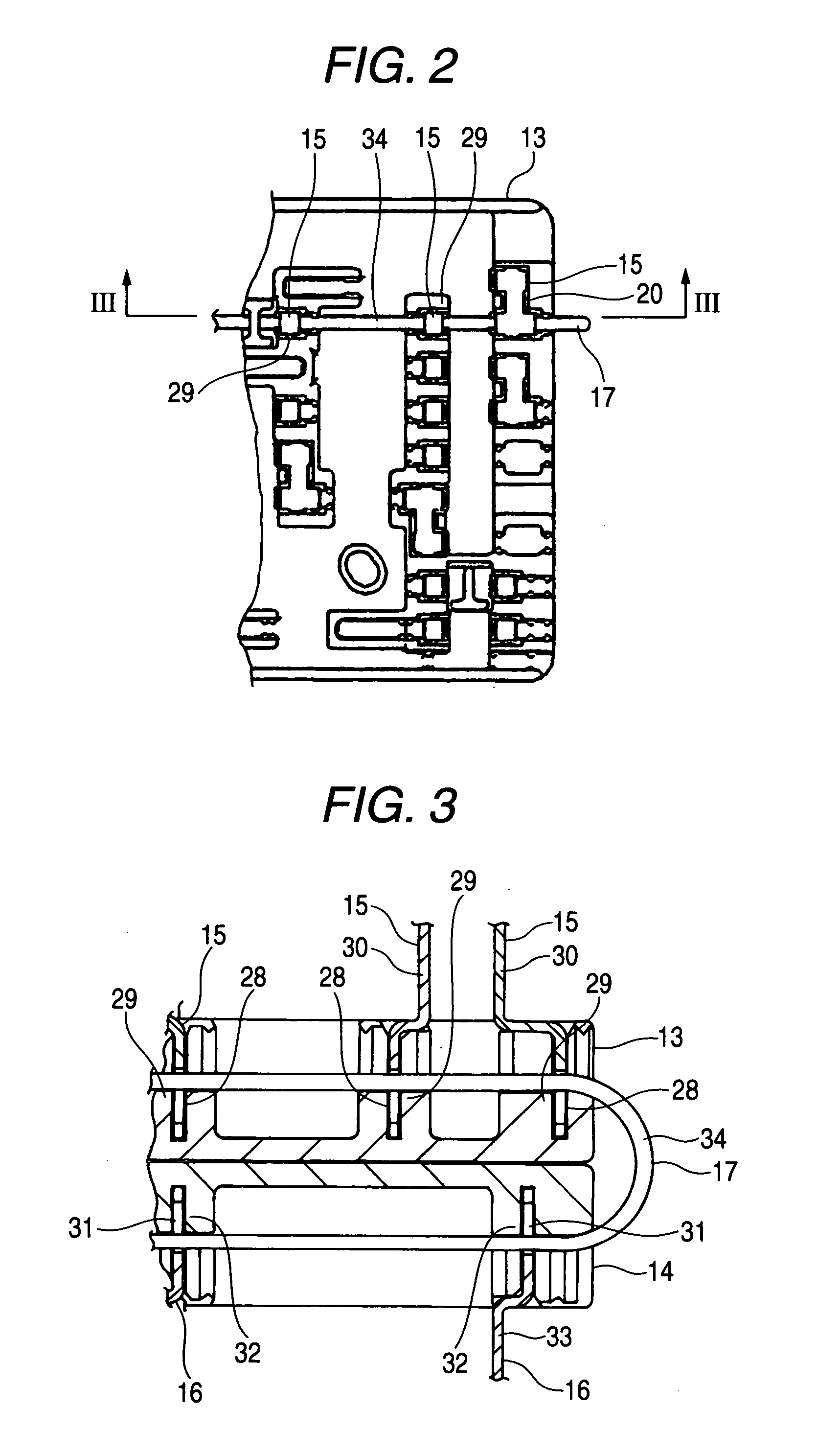
[0024]FIG. 1 is an exploded, perspective view of one preferred embodiment of an electric connection box of the invention, FIG. 2 is a plan view of a wiring board used in the electric connection box of FIG. 1, FIG. 3 is a cross-sectional view taken along the line III—III of FIG. 2, FIG. 4 is a plan view of the wiring boards in a developed condition, showing a condition of use of a connecting wire in the electric connection box of FIG. 1, FIG. 5 is a perspective view showing the electric connection boxes of FIG. 1 combined together, and FIGS. 6 and 7 are plan views of the wiring board in a developed condition, showing different forms of use from that of FIG. 4.

[0025]As shown in FIG. 1, the electric connection box 10 of this embodiment comprises a first cover 11, a second cover 12, the first wiring board 13, the second wiring board 14, a plurality of first wiring board-s...


PUM


Abstract

An electric connection box includes a first cover and a second cover each having connector mounting portions, a first wiring board and a second wiring board which are mounted in a stacked manner between the first and second covers, a plurality of press-contacting terminals which are disposed in the connector mounting portions of the first and second covers, and are inserted in the first and second wiring boards, and a connecting wire which is selectively connected to the press-contacting terminals, and is arranged to extend over the first and second wiring boards when the first and second wiring boards are stacked together.

Description

BACKGROUND OF THE INVENTION[0001]1. Field of the Invention[0002]This invention relates to an electric connection box used, for example, in the interior wiring of an automobile.[0003]2. Related Art[0004]In one known conventional electric connection box, a wiring plate, having wires laid thereon, and an ECU board, having electronic parts soldered thereto, are received in a stacked manner within an upper case having connector mounting portions, and press-contacting portions of press-contacting terminals are connected to the wires laid on the wiring plate, and tab terminal portions project into the connector mounting portions, and a lower open portion of the upper case is closed by a lower case, and wiring plate engagement recesses are formed in inner surfaces of opposite side walls of the upper case, and engagement projections are formed on side walls of the wiring plate (see, for example, Japanese Patent Publication No. JP-A-2001-320814 (Pages 2 to 3, FIG. 1)).[0005]In another known c...

Claims


Application Information

Patent Timeline
Patent Type & Authority Patents(United States)
IPC IPC(8): H01R12/00
CPCB60R16/0238H01R9/2458Y10S439/949
Inventor ISHIGURO, MASAAKINISHIHARA, KAZUEAMANO, MASATAKA
Owner YAZAKI CORP
Why Eureka
Try Eureka