Hydraulic control for powershift transmission

a technology of hydraulic control circuit and transmission line, applied in mechanical equipment, transportation and packaging, gearboxes, etc., can solve the problems of reduced operating performance, insufficient transmission gear ratio for launching, and little design flexibility for accommodating, so as to reduce the cost of the control system and achieve greater independence.

Inactive Publication Date: 2014-04-15
FORD GLOBAL TECH LLC
View PDF8 Cites 4 Cited by
  • Summary
  • Abstract
  • Description
  • Claims
  • Application Information

AI Technical Summary

Benefits of technology

[0012]The use multiplexed on / off solenoids reduces cost of the control system compared to the cost of conventional variable force solenoids.
[0013]The electro-hydraulic control includes stand-alone, clutch control VFSs, allowing greater independence between clutch control and synchronizer selection. The control has a dedicated VFS for synchronizer flow and pressure control, and synchronizer selection is a result of the valve selection network, which receives input signal from the clutch solenoids and clutch cooling control solenoids.

Problems solved by technology

Due to engine downsizing and boosting for a given vehicle size, boost is not present at launch causing potentially insufficient transmission gear ratio for launching.
A powershift transmission generally has a specific number of gears and provides little design flexibility for accommodating an increase in the number of gears to five, six or seven speeds.
Some designs have relied on multiplexing clutch controls with synchronizer control in an attempt to deduce cost, which results in reduced operating performance, such as longer shift period, loss of repeatable high quality shifts, and an increased number of failure states.

Method used


Image

  • Hydraulic control for powershift transmission
  • Hydraulic control for powershift transmission
  • Hydraulic control for powershift transmission

Examples


Embodiment Construction

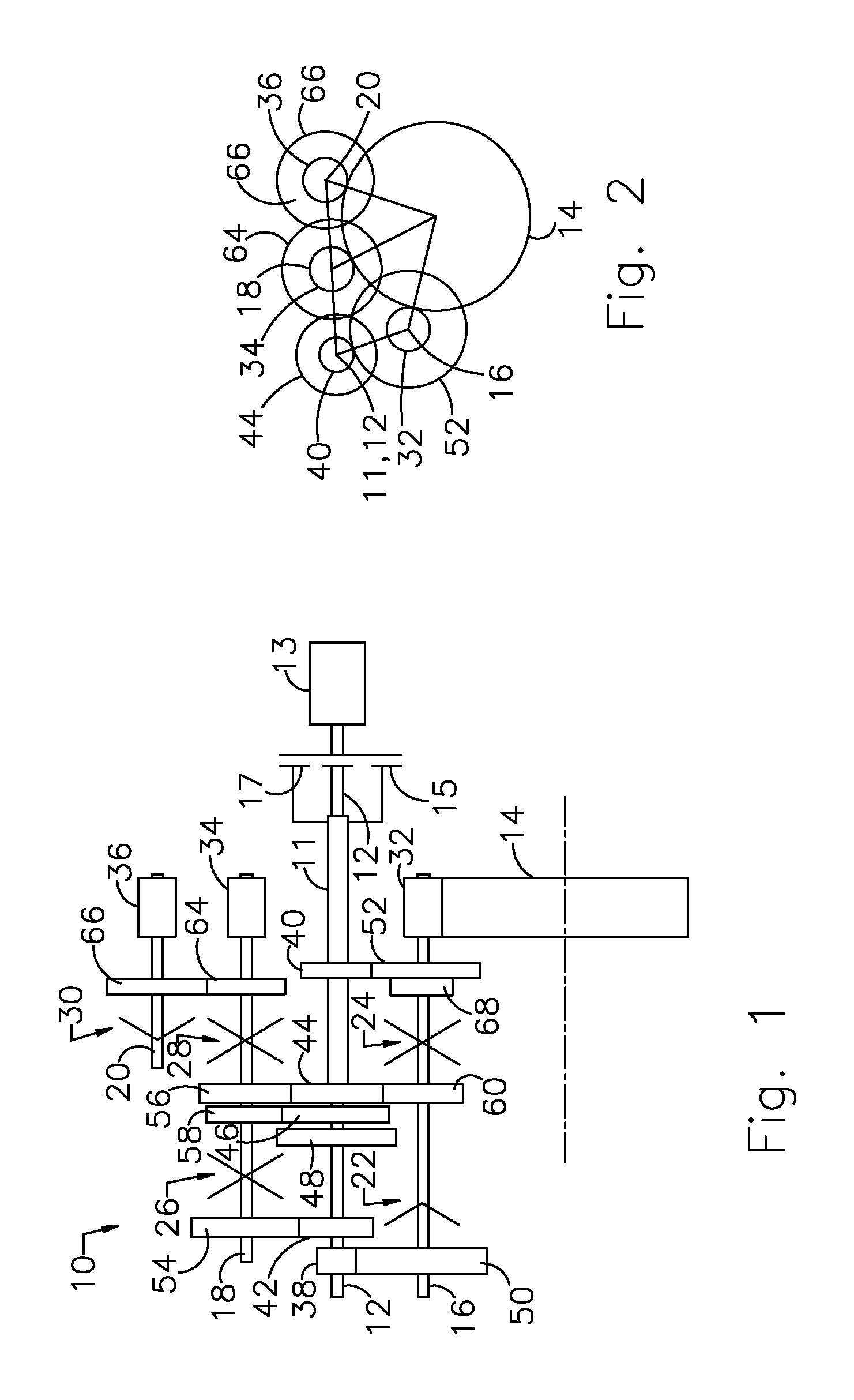
[0020]Referring now to FIG. 1, a powershift transmission 10 includes first and second coaxial input shafts 11, 12, an output gear 14 driveably connected to the vehicle wheels (not shown); first, second and third layshafts 16, 18, 20, respectively; a 1-neutral synchronizer 22; a 6-2 synchronizer 24; a 3-5 synchronizer 26; a 4-R synchronizer 28; and a L synchronizer 30. Outer shaft 11 is driveably connected to an engine 13 through an input clutch 15. Inner shaft 12 is driveably connected to the engine through an input clutch 17.

[0021]Each layshaft 16, 18, 20 includes an output pinion 32, 34, 36, secured to the respective layshaft. Each synchronizer is secured to the layshaft on which it is supported and includes a selector sleeve having a neutral position from which it is moved axially along the shaft to secure a gear to the shaft. Input clutches 15, 17 include sets of clutch plates, which alternately engage and disengage mutually.

[0022]Secured to input shaft 12 are input pinions 38, ...


PUM


Abstract

A method for controlling a transmission includes using signals of first solenoids to control first and second clutches, servos of first gears and servos of second gears, using signals of a second solenoid to establish a flow rate to cool the clutches and to actuate the servo that is associated with a selected gear, and using signals of a third solenoid to direct the flow rate to one of the clutches and to engage the selected gear.

Description

BACKGROUND OF THE INVENTION[0001]1. Field of the Invention[0002]This invention relates generally to a powertrain for a motor vehicle, particularly to the hydraulic control circuit of powershift transmission located in the powertrain.[0003]2. Description of the Prior Art[0004]A dual clutch transmission (DCT), also called a powershift transmission, is a geared mechanism employing two input clutches used to produce multiple gear ratios in forward drive and reverse drive. It transmits power continuously using synchronized clutch-to-clutch shifts.[0005]The transmission incorporates gearing arranged in a dual layshaft configuration between the transmission input and its output. One input clutch transmits torque between the input and a first layshaft associated with certain gears; the other input clutch transmits torque between the transmission input and a second layshaft associated with the other gears. The transmission produces gear ratio changes by alternately engaging a first input clu...

Claims


Application Information

Patent Timeline
Patent Type & Authority Patents(United States)
IPC IPC(8): B60W10/04F16H3/08F16H61/26B60W10/02
CPCF16H61/688F16H61/2807Y10T74/19228Y10T74/20024
Inventor FRAIT, STEVEN A.THOMAS, STEVEN G.
Owner FORD GLOBAL TECH LLC
Why Eureka
Try Eureka