Method and system for heating a vehicle

a vehicle and heating technology, applied in the direction of heating apparatus, defrosting, domestic cooling apparatus, etc., can solve the problems of increasing system cost and complexity, and reducing system complexity, so as to increase system cost and complexity

Active Publication Date: 2019-01-22
FORD GLOBAL TECH LLC
View PDF25 Cites 4 Cited by
  • Summary
  • Abstract
  • Description
  • Claims
  • Application Information

AI Technical Summary

Benefits of technology

[0003]Environmental conditions of a vehicle's passenger compartment may be adjusted via a heat pump. The heat pump may include expansion valves that have electrically controlled variable orifices (e.g., electrically operated variable expansion valves). By adjusting orifice area, refrigerant flow through the heat pump may be controlled to provide desired passenger compartment environmental conditions. However, expansion valves that have electrically controlled variable orifices may be expensive. Further, a controller including sensors and instructions to operate the expansion valve may further increase system cost and complexity.
[0005]By applying thermal expansion valves in a climate control system instead of electrically operated variable expansion valves, it may be possible to provide the technical result of reducing climate control system cost while maintaining desirable climate control system operating modes. For example, thermal expansion valves may be applied in a system that operates in cooling mode, heating mode, dehumidification mode, and de-icing mode. Use of electrically operated variable expansion valves may be facilitated by strategic placement of a coolant receiver in the climate control system. In one example, the receiver may be fluidically coupled to an exterior heat exchanger so that refrigerant enters the receiver in a saturated state, thereby reducing the possibility of vaporizing liquid refrigerant stored in the receiver.
[0006]The present description may provide several advantages. Specifically, the approach may improve passenger compartment heating and cooling of electric and hybrid vehicles. Further, the approach may reduce system cost. Further still, the approach may reduce system complexity.

Problems solved by technology

However, expansion valves that have electrically controlled variable orifices may be expensive.
Further, a controller including sensors and instructions to operate the expansion valve may further increase system cost and complexity.
Further still, the approach may reduce system complexity.

Method used


Image

  • Method and system for heating a vehicle
  • Method and system for heating a vehicle
  • Method and system for heating a vehicle

Examples


Embodiment Construction

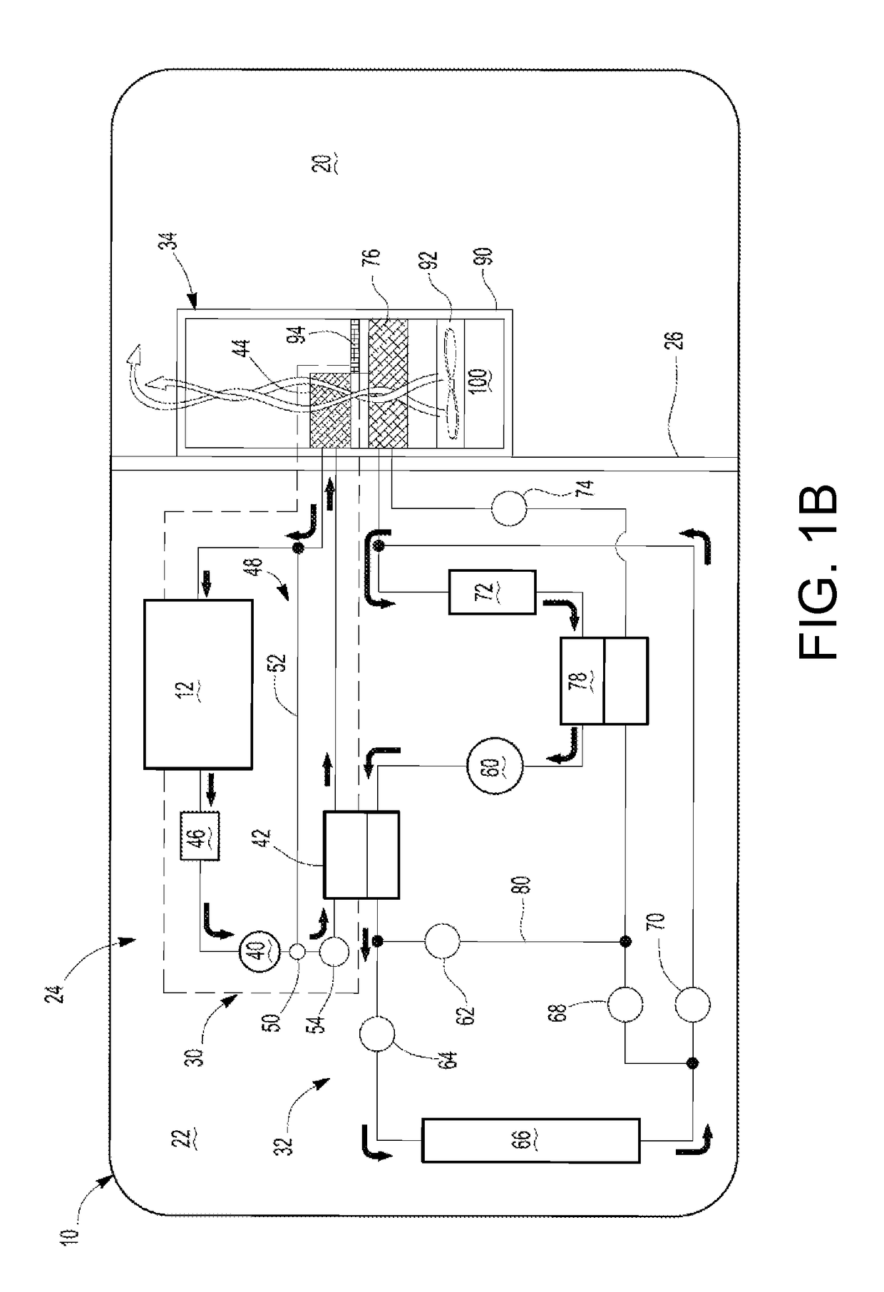
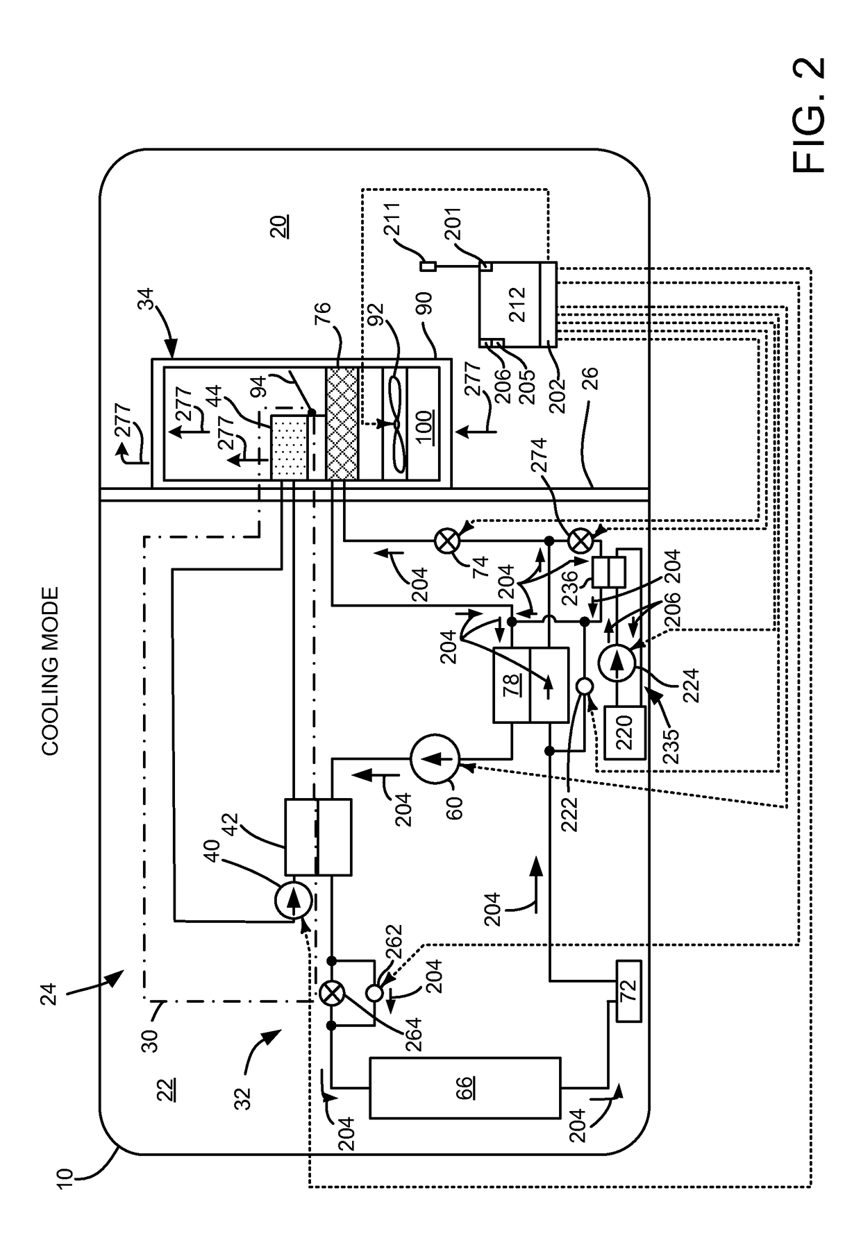
[0017]The present description is related to providing a climate control system for a vehicle. The vehicle climate control system may be included in an electric or hybrid vehicle as is shown in FIG. 1A. In one example, the climate control system includes a thermal expansion valve (TXV) positioned upstream of an interior heat exchanger as shown in FIG. 1B. Alternatively, the climate control system may be configured with a TXV upstream of the interior heat exchanger in the system of FIG. 2. The system of FIG. 2 may be operated in the modes indicated in FIGS. 2-5. A method for transitioning between the various operating modes is shown in FIG. 6.

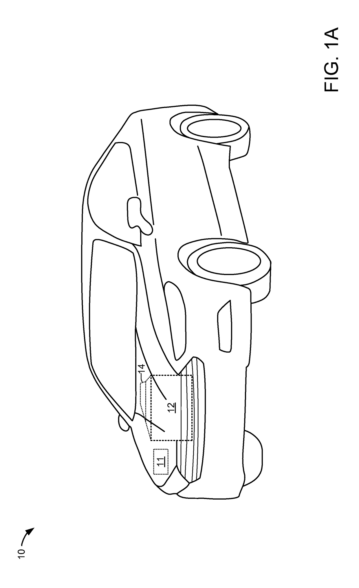
[0018]Referring to FIG. 1A, a vehicle 10 including an engine 12, an electrical machine 14, and an electrical energy storage device 11 is shown. In one example, the vehicle may be propelled solely via the engine 12, solely via the electrical machine 14, or by both the engine 12 and the electrical machine 14. The electrical machine may be supplied ...


PUM


Abstract

Methods and systems for providing controlling environmental conditions in a passenger compartment of a vehicle are presented. In one example, various low cost expansion valves are included in a system that has a receiver positioned downstream of an exterior heat exchanger to provide a climate control system with heating, cooling, dehumidification, and de-icing modes.

Description

CROSS REFERENCE TO RELATED APPLICATIONS[0001]The present application is a continuation-in-part of U.S. patent application Ser. No. 14 / 010,057, entitled “CLIMATE CONTROL SYSTEM,” filed on Aug. 26, 2013, the entire contents of which are hereby incorporated by reference for all purposes.FIELD[0002]The present description relates to methods and a system for providing climate control for a vehicle. The methods and system may be particularly useful for vehicles that are solely electrically propelled or vehicles that include hybrid powertrains.BACKGROUND AND SUMMARY[0003]Environmental conditions of a vehicle's passenger compartment may be adjusted via a heat pump. The heat pump may include expansion valves that have electrically controlled variable orifices (e.g., electrically operated variable expansion valves). By adjusting orifice area, refrigerant flow through the heat pump may be controlled to provide desired passenger compartment environmental conditions. However, expansion valves th...

Claims


Application Information

Patent Timeline
Patent Type & Authority Patents(United States)
IPC IPC(8): F25B13/00B60H1/00F25D21/06
CPCB60H1/00921B60H2001/00928
Inventor GEBBIE, JAMES GEORGEMARANVILLE, CLAY WESLEYBLATCHLEY, TIMOTHY NOAH
Owner FORD GLOBAL TECH LLC
Why Eureka
Try Eureka