Buried steel pipeline coating stripping and corrosion test system under stress and stray current coupling effect

A stray current, corrosion test technology, applied in the direction of weather resistance/light resistance/corrosion resistance, measuring devices, instruments, etc., can solve problems such as single function, inability to simulate the actual working conditions of buried pipelines, and inability to combine organically.

Inactive Publication Date: 2013-11-27
BEIJING UNIV OF TECH
View PDF7 Cites 16 Cited by
  • Summary
  • Abstract
  • Description
  • Claims
  • Application Information

AI Technical Summary

Problems solved by technology

[0003] In order to overcome the defects that the existing stress stretching device cannot simulate the actual working conditions of the buried pipeline, the pipeline stray current corrosion experiment device has a single function, and the two cannot be organically combined, the present invention pushes the piston through the force applying handle 1 and the loading screw 2 The component extrudes the working medium so that the pipeline 14 is subjected to stress; the constant current source 27, the pulse signal generator 25, and the intelligent interrupter 28 are used to generate DC, AC, and AC-DC mixed current stray current; the constant voltage source 22 is used to generate the cathodic protection potential; Utilize electrochemical workstation 30 to carry out electrochemical test to pipeline 14 coating; Utilize conductivity meter 23 and pH meter 24 to configure the soil solution of different pH and conductivity and monitor the change of soil solution parameter during experiment

Method used


Image

  • Buried steel pipeline coating stripping and corrosion test system under stress and stray current coupling effect
  • Buried steel pipeline coating stripping and corrosion test system under stress and stray current coupling effect
  • Buried steel pipeline coating stripping and corrosion test system under stress and stray current coupling effect

Examples


Embodiment Construction

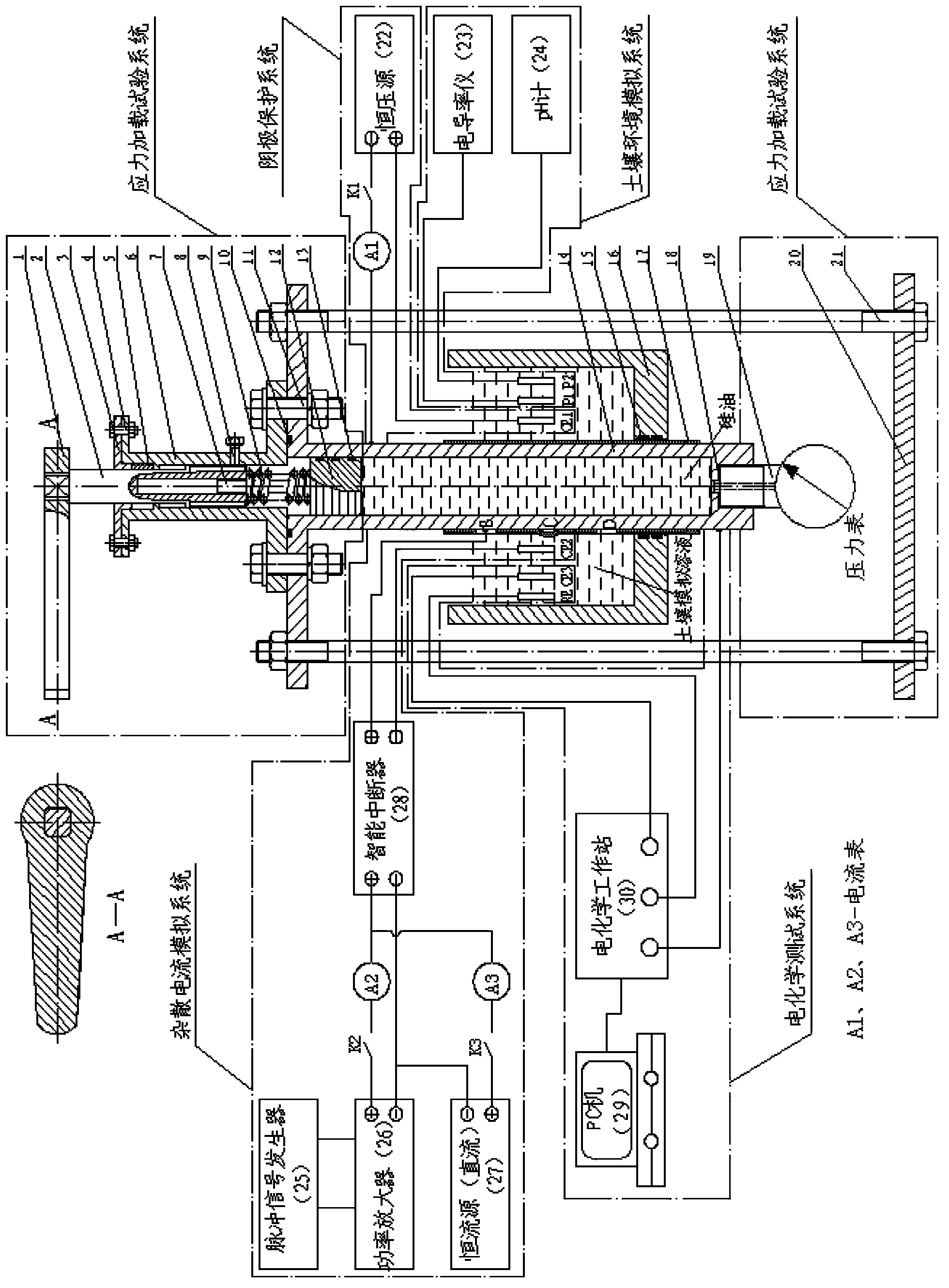
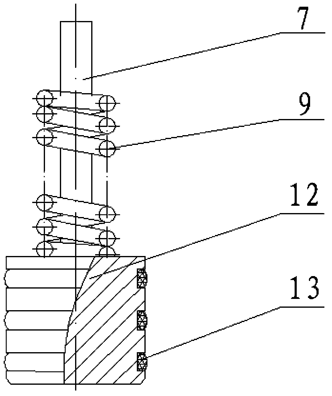
[0025] exist figure 1 As shown in the specific structural cross-sectional view of a buried steel pipeline coating stripping and corrosion test system of the present invention under the coupled action of stress and stray current, silicone oil is poured into the pipeline 14 to build a stress loading test system. Push the force application handle 1 to drive the loading screw 2 to rotate through the screw drive to generate an axial force to compress the coil spring 9 and then transmit the force to the piston 12. The piston 12 compresses the silicone oil to generate pressure so that the pipeline 14 is subjected to stress. Observe the pressure gauge 19. Stop pushing the force-applying handle 1 until the specified pressure, and tighten the bolt 8 to prevent the loading screw 2 from rotating. When the stress on the pipeline 14 needs to be changed, the bolt 8 is unscrewed, and the force application handle 1 is pushed until the required pressure is reached, and then the bolt 8 is tighte...


PUM


Abstract

The invention relates to a buried steel pipeline coating stripping and corrosion test system under a stress and stray current coupling effect, and belongs to the field of pipeline corrosion and coating stripping detection. The test system comprises a stress loading test system, a soil environment simulation system, a stray current simulation system, a cathode protection system, and an electrochemistry test system. With the test system, actual working conditions of a buried steel pipeline can be simulated, corrosion law experiments under different influence factors (soil resistivity/conductivity, soil pH value, different stress levels, stray current types/intensity, damage area/stripping area, and the like) can be performed on pipelines, a pipeline cathode stripping experiment and an experiment of stripping produced on a coating damage position due to stray current inflow can be performed, and an experiment of underlayer corrosion caused by pipeline cathode stripping and an experiment of corrosion (including stray current corrosion) caused by coating damage can be performed. The method can be suitable for buried steel pipeline coating stripping and corrosion detection laboratory researches and preliminary studies of pipeline production enterprises.

Description

technical field [0001] The invention belongs to the field of pipeline corrosion and coating stripping detection, in particular to a buried steel pipeline coating stripping and corrosion test system under the coupled action of stress and stray current. Background technique [0002] With the increasing complexity of buried pipelines and increasing oil pressure, the impact of stray currents generated by high-voltage power transmission systems and AC / DC traction systems continues to increase. The problem of pipeline corrosion and coating peeling has been paid more and more attention. Due to the limitations of many objective factors, the research on stray current corrosion and coating peeling of buried pipelines is mainly based on laboratory research. At present, there are single tensile stress test devices and stray current corrosion test devices in China, but the existing tensile stress test devices are difficult to simulate the real force of buried pipelines, and the existing...

Claims


Application Information

Patent Timeline
Patent Type & Authority Applications(China)
IPC IPC(8): G01N17/02
Inventor 王新华唐兴华王力伟王翠郭真真
Owner BEIJING UNIV OF TECH
Why Eureka
Try Eureka