Air source heat pump water circulation heat exchange drying system

An air source heat pump and water circulation technology, applied in drying, drying machines, heating devices, etc., can solve the problems of large size and energy consumption, and achieve the effects of reducing humidity, uniform heating form, and reducing energy consumption

Active Publication Date: 2015-06-10
广东环球净化科技有限公司
View PDF5 Cites 0 Cited by
  • Summary
  • Abstract
  • Description
  • Claims
  • Application Information

AI Technical Summary

Problems solved by technology

Although this type of heat pump drying equipment can replace traditional coal heating or electric heating drying equipment, and has made great progress in energy saving and environmental protection, the working process of the heat pump also consumes energy. How to further improve the efficiency of heat pump energy conversion, Make fuller use of air energy, which is still a technical problem faced by heat pump drying equipment

Method used


Image

  • Air source heat pump water circulation heat exchange drying system
  • Air source heat pump water circulation heat exchange drying system
  • Air source heat pump water circulation heat exchange drying system

Examples


Embodiment 1

[0020] This embodiment is an air source heat pump water circulation heat exchange drying system, its composition and connection relationship are as attached figure 1 shown.

[0021] The air source heat pump water circulation heat exchange system given in this embodiment includes a hot water circulation loop and a hot water heat exchange circulation loop, and also includes a cooling water circulation loop and a cold water condensation circulation loop, as shown in the attached figure 1 As shown, the hot water circulation loop includes a compressor 10, an evaporator 11, a throttle valve 12, a condenser 13, a hot water storage tank 14, and connecting pipes, and the hot water heat exchange circulation loop includes a hot water storage tank 14, Heating heat exchanger 15, hot water pipeline 16, circulating water pump 17; figure 1 As shown, the cooling water circulation loop includes a compressor 20, an evaporator 21, a throttle valve 22, a condenser 23, a cold water storage tank 24...

Embodiment 2

[0023] This embodiment is a practical air source heat pump water circulation heat exchange drying system, its composition and connection relationship are as attached figure 2 shown.

[0024] In this embodiment, the compressor, evaporator, throttle valve, and condenser in the heating water circulation loop are integrated into a hot water heat pump unit 101, and the compressor, evaporator, throttle valve, and condenser in the cooling water circulation loop are also integrated The device is integrated into a chilled water heat pump unit 103.

[0025] In this embodiment, the condenser of the cooling water heat pump unit 103 and the evaporator of the heating water heat pump unit 101 are sealed and confined in the same space by connecting the air guide device 102 in the form of a box body, so that the cooling water heat pump unit generates heat during operation. The heat energy is used again by the hot water heating heat pump unit in the hot water heating process, which improves t...

Embodiment 3

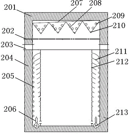
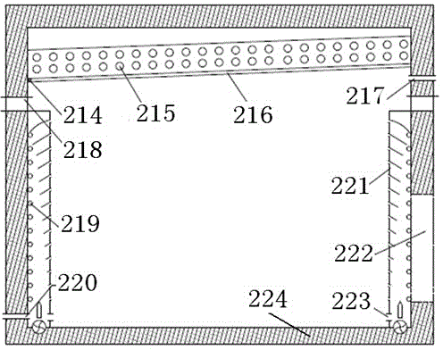
[0031] This embodiment gives a structural design example of a practical drying room, the transverse section of the structure is as attached image 3 , the longitudinal section of its structure is as attached Figure 4 shown.

[0032] In this embodiment, the drying room is composed of heat-insulating side wall 204, heat-insulating roof 201, and ground base insulation layer 224. A wall heat-resisting layer 203 is arranged between the heat-insulating side wall 204 and the heat-insulating roof 201, and the heat exchanger is heated. The capillary 205 is arranged along the facade of the thermal insulation side wall 204, and an upright turbulence plate 221 is set on the side of the capillary 205 towards the center of the drying room. Groove or through hole 212, and wind deflector 211 is arranged at the upper edge of each through groove or through hole 212, and the length of wind deflector 211 increases along with the rise of its level, at the bottom of drying room 1. A fan 213 is a...


PUM


Abstract

The invention relates to an air source heat pump water circulation heat exchange drying system, which consists of two heat pump units with different applications, wherein one heat pump unit is used for making hot water and the other heat pump unit is used for making cold water. A hot water making unit, a hot water tank and a hot water pipeline form a hot water making circulation loop, the hot water tank, a heating heat exchanger, a circulating water pump and the hot water pipeline form a hot water heat exchange circulation loop, the heating heat exchanger transfers the heat of hot water to air to heat the air in a drying room; a cold water making unit, a cold water tank and a cold water pipeline form a cold water making circulation loop, the cold water tank, a dehumidifying heat exchanger, a circulating water pump and the cold water pipeline form a cold water condensation circulation loop, and due to the cold water running in the dehumidifying heat exchanger, wet and hot air in the drying room is condensed into water on the surface of the dehumidifying heat exchanger while meeting the dehumidifying heat exchanger and is discharged out of the drying room. According to the air source heat pump water circulation heat exchange drying system disclosed by the invention, hot air discharged by a refrigerating circulating condenser is guided into a heating circulating evaporator, so that the whole energy efficiency of the system is improved; the drying room provided by the invention has the advantages of remarkable heating and dehumidifying effect, uniform room temperature and excellent application prospect.

Description

technical field [0001] The invention relates to the technical field of drying equipment, in particular to a closed drying system utilizing heat pump technology. Background technique [0002] Heat pump drying equipment can be divided into three categories: open type, semi-open type and closed type according to the degree of connection between the drying medium and the external environment. Heat pump technology is gradually being applied to drying equipment due to its energy saving and environmental protection characteristics. The traditional heat pump drying equipment only uses the basic performance of the heat pump to convert the heat energy in the air source into hot air at a certain temperature, and then passes the hot air into the drying room to dry items. Although this type of heat pump drying equipment can replace traditional coal heating or electric heating drying equipment, and has made great progress in energy saving and environmental protection, the working process...

Claims


Application Information

Patent Timeline
Patent Type & Authority Patents(China)
IPC IPC(8): F26B23/10F25B29/00
Inventor 王高元周岳
Owner 广东环球净化科技有限公司
Why Eureka
Try Eureka