Surface airbrushing method and airbrushing head for stereoscopic object

A technology of three-dimensional objects and nozzles, used in power transmission devices, printing, transfer materials, etc., can solve the problems of inability to further improve the transmission efficiency, consuming a lot of manpower, affecting the efficiency of mass production, etc., and achieving outstanding substantive characteristics. , easy to control, clear outline effect

Inactive Publication Date: 2014-04-16
汤振华
View PDF6 Cites 19 Cited by
  • Summary
  • Abstract
  • Description
  • Claims
  • Application Information

AI Technical Summary

Problems solved by technology

[0006] However, for equipment with a large production volume, it will consume a lot of manpower to manually position the printing medium every time, and because manual positioning takes a certain amount of time, the efficiency of transmission cannot be further improved, which will affect the efficiency of mass production

Method used


Image

  • Surface airbrushing method and airbrushing head for stereoscopic object
  • Surface airbrushing method and airbrushing head for stereoscopic object
  • Surface airbrushing method and airbrushing head for stereoscopic object

Examples


Embodiment 1

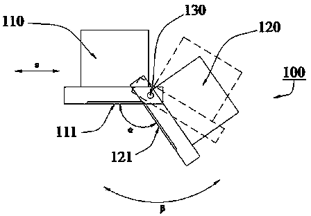
[0031] Embodiment 1: as figure 1 A three-dimensional surface inkjet nozzle 100 shown includes two groups of nozzle modules 110, 120 and an inkjet control system (not shown in the figure). The inkjet control system described above controls the change of the angle α between the nozzle modules 110 and 120 . This embodiment also includes a rotation mechanism (not shown) that controls the rotation of the entire inkjet nozzle 100 and a translation mechanism (not shown) that controls the translation of the entire inkjet nozzle 100. The inkjet control system controls the rotation mechanism and The translation mechanism drives the change of the overall position s and the change of the angle β of the inkjet nozzle 100, as shown in the figure.

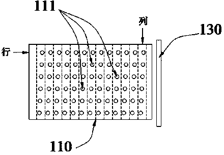
[0032] combine figure 1 and figure 2 As shown, nozzle holes 111 and 121 are distributed in matrix on the nozzle modules 110 and 120 . Taking the nozzle module 110 as an example, such as figure 2 As shown, each row of nozzle holes 111 is a ...

Embodiment 2

[0036] Embodiment 2: as Figure 6 and 8 A three-dimensional object surface inkjet nozzle 200 is shown, including three groups of nozzle modules 210, 220, 230 and an inkjet control system (not shown in the figure), and the three groups of nozzle modules 210, 220, 230 also pass Hinged together, the inkjet control system controls the angle change between the nozzle modules 210 , 220 and between the nozzle modules 210 , 230 .

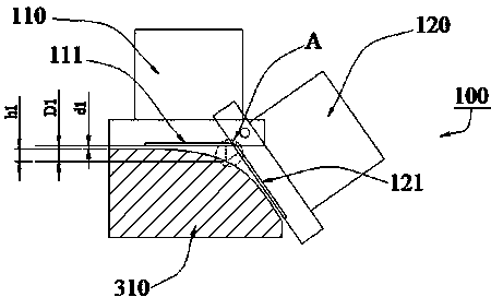
[0037] Such as Figure 6 As shown, in the case that the cross section of the printing medium 330 is isosceles trapezoidal, the inkjet control system controls the nozzle modules 210, 220, and the angle between the nozzle modules 210, 230 changes, so that the inkjet nozzle 200 adapts to The surface profile of the printing medium 330, so that the distance between the three groups of nozzle modules 210, 220, 230 and the surface of the printing medium 330 is between 1 mm and 4 mm, and the distance difference between any nozzle hole in operation and the printin...


PUM


Abstract

The invention relates to the field of airbrushing equipment used for airbrushing the surface of a stereoscopic object and provides an airbrushing method and an airbrushing head which are used for airbrushing the surface of a special-shaped stereoscopic object and are high in airbrushing efficiency in order to overcome the defects in the prior art. The airbrushing head structurally comprises at least two sets of airbrushing head modules, airbrushing holes are distributed in each set of airbrushing head module in a matrix mode, and a certain angle exists between the airbrushing head modules. According to the method, the angle between the airbrushing modules is controlled to change so that the distance between any working airbrushing hole in the airbrushing head modules and airbrushing points on a printing medium is 1-15mm. The distance between the airbrushing holes and the concave-convex surface of the printing medium is kept in a reasonable range, and it is ensured that an airbrushed picture is not deformed.

Description

technical field [0001] The invention relates to the field of inkjet equipment for inkjet painting on the surface of three-dimensional objects, more specifically, a method for inkjet nozzles and an inkjet nozzle for inkjet printing on the surface of a three-dimensional object. Background technique [0002] Printing on three-dimensional objects by large-scale printers or inkjet printers has been a common technical means, such as existing ceramic inkjet printers or wood board inkjet printers. This type of printing medium is generally a flat plate structure, that is, the inkjet surface is flat, so that the distance between all the nozzle holes on the inkjet nozzle and the inkjet surface can be guaranteed to be the same, and the stroke of the ink ejected from the nozzle holes is the same, which can ensure the quality of inkjet printing. [0003] However, for non-planar or inclined printing media, the above method is not feasible. This is because the inkjet printing surface is no...

Claims


Application Information

Patent Timeline
Patent Type & Authority Applications(China)
IPC IPC(8): B41J2/14B41J3/407
CPCB41J3/4073B41J25/316
Inventor 汤振华
Owner 汤振华
Why Eureka
Try Eureka