Control method of internal pressure of elevator car

An elevator car, internal pressure technology, applied to elevators, lifts, transportation and packaging in buildings, etc., can solve the problems of complex control device structure and control method, rising cost, etc., to simplify the structure and control method, eliminate Effects of ear blockage and discomfort

Active Publication Date: 2014-06-18
HITACHI LTD
View PDF15 Cites 12 Cited by
  • Summary
  • Abstract
  • Description
  • Claims
  • Application Information

AI Technical Summary

Problems solved by technology

That is, since the pressurization and decompression in the elevator car are frequently switched, the structure of the control device and the control method become complicated, and there is a problem that the cost increases.

Method used


Image

  • Control method of internal pressure of elevator car
  • Control method of internal pressure of elevator car
  • Control method of internal pressure of elevator car

Examples


no. 1 example

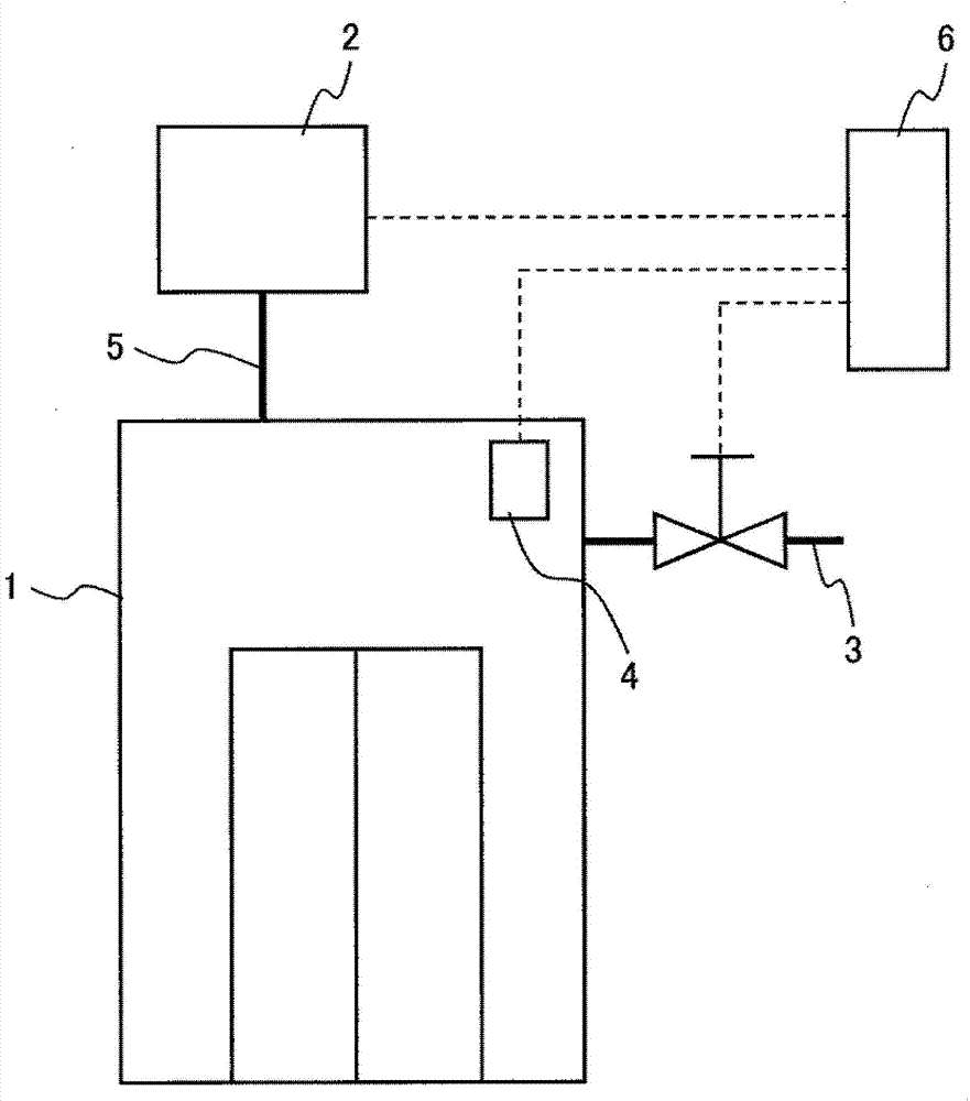
[0034] figure 1 It is a block diagram of the elevator apparatus concerning the 1st Example of this invention. like figure 1 As shown, the elevator equipment of the first embodiment consists of an elevator car 1, one or more air blowers 2 for pressurizing and decompressing the interior of the elevator car 1, a piping 5 connecting the elevator car 1 and the air blower 2, and passing through The air blower 2 changes the pressure in the elevator car maintained at a positive pressure state or a negative pressure state toward the atmospheric pressure side, a pressure regulating valve 3 for measuring the pressure inside the elevator car 1, and the pressure measured by the pressure measuring device 4. The internal pressure of the elevator car is controlled by the control device 6 of the blower 2 and the pressure regulating valve 3.

[0035] The air blower 2 sends air to the elevator car 1 or discharges air from the elevator car 1 through the piping 5, thereby increasing or reducin...

no. 2 example

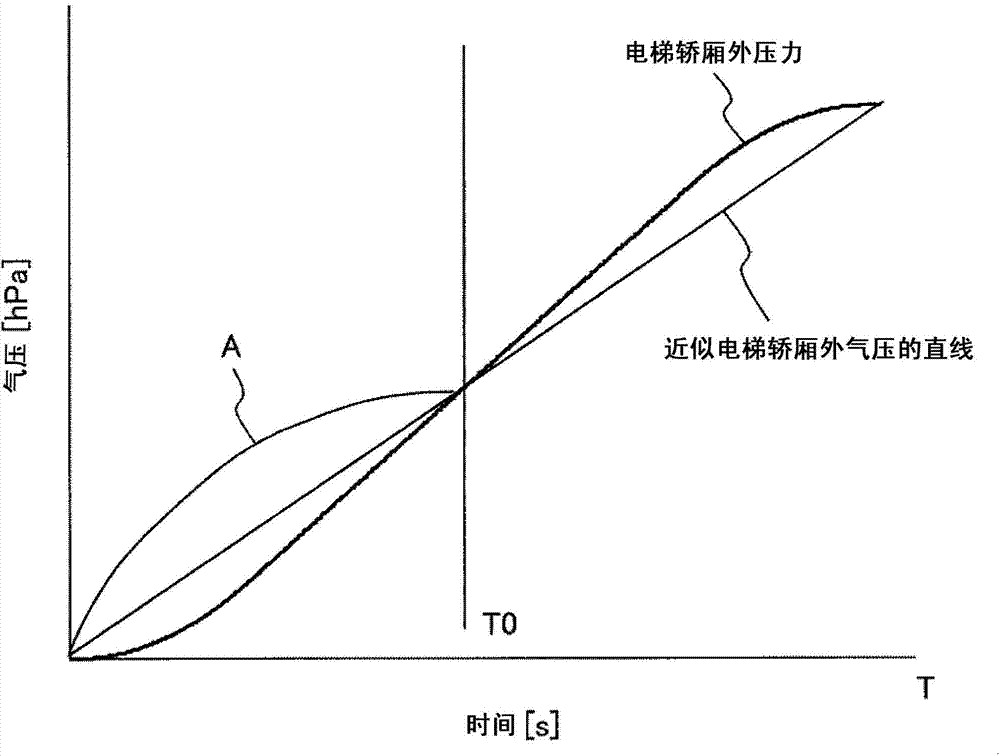
[0046] Image 6 It is an explanatory diagram of the pressure control mode according to the second embodiment of the present invention. exist Image 6 Among them, the horizontal axis represents time, and the vertical axis represents the elevator car external pressure along with the position change of the elevator car 1 in the elevator lifting, as mentioned above, according to the initial end of the S-shaped pressure curve of the elevator car external pressure and The end end approximates the S-shaped pressure curve of the elevator car external pressure to a straight line to obtain an approximate straight line, and defines the approximate straight line as the approximate straight line of the elevator car external pressure.

[0047] In a second embodiment, the step-like pressure change pattern of the elevator car internal pressure is configured to vary in the inner region between the S-shaped pressure curve and the approximately straight line of the elevator car external pressur...

no. 3 example

[0049] Figure 7 It is an explanatory diagram of a comparative example of the pressure control mode according to the third embodiment of the present invention. Figure 8 It is an explanatory diagram of the pressure control mode according to the third embodiment of the present invention.

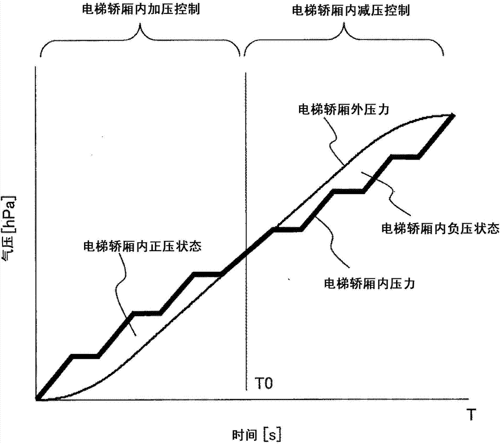
[0050] In the first embodiment, the ladder shape of the internal pressure of the elevator car is as follows Figure 7 As shown, it consists of two parts: the first pressure change portion (pressure change rate P1 / T1) and the second pressure change portion (pressure change rate 0). The purpose is to change the pressure in the first pressure changing portion and keep the pressure constant in the second pressure changing portion, thereby prompting the passenger to perform a swallowing action.

[0051] For the step shape of the internal pressure of the elevator car, the present inventors calculated the first pressure change rate (P1 / T1), the second pressure change rate (P2 / T2), the pressure cha...


PUM


Abstract

When an elevator is lifted, an ear blockage phenomenon occurs due to changes of an internal pressure of an elevator car. The internal pressure of the elevator car is changed repeatedly between two different pressure change rates so that a control method inducing passengers' swallow actions can effectively ease the ear blockage phenomenon. However, in existing control methods, the pressure in the elevator car needs to be repeatedly switched to be a positive pressure and a negative pressure relative to the atmospheric pressure in a short time, and problems that a structure of a control device and a control method are complex exist. When the elevator goes down, a positive pressure state in the elevator car is only used to form stair-stepping pressure control in the first half of the running time (TT0). Therefore, the pressure control device only needs to implement switchover once, that is to say, a pressurized state is switched into a pressure reducing state, and the pressure control can be realized.

Description

technical field [0001] The present invention relates to a method for controlling the internal pressure of an elevator car, in particular to a pressure control method for reducing the ear blockage phenomenon caused by the change of the internal pressure of the elevator car when going up and down in a super-high-speed or super-long-travel elevator . Background technique [0002] In high-rise buildings, etc., elevators with high-speed elevator cars with large strokes are used. In the above-mentioned elevators, sudden pressure changes in the elevator car are likely to occur, causing ear blockage and discomfort to passengers. In order to improve this phenomenon, various solutions have been proposed in the prior art. [0003] As the background technology of this technical field, a kind of elevator equipment used in the super high-rise building is disclosed in the patent document 1, in the elevator equipment, by making the air pressure in the elevator car be stepped The state cha...

Claims


Application Information

Patent Timeline
Patent Type & Authority Applications(China)
IPC IPC(8): B66B5/00B66B11/02
CPCB66B5/00B66B11/02
Inventor 河村阳右石文良萩原高行宫田弘市三好宽
Owner HITACHI LTD
Why Eureka
Try Eureka