Optical converter for high luminances

A converter and high-brightness technology, applied in the field of optical converters, can solve problems such as light share decline, and achieve the effects of small emission spots, good light confinement, and high brightness

Inactive Publication Date: 2014-07-02
SCHOTT AG
View PDF11 Cites 5 Cited by
  • Summary
  • Abstract
  • Description
  • Claims
  • Application Information

AI Technical Summary

Problems solved by technology

However, if the material scatters so strongly that the excitation light is also diffusely reflected before it is absorbed, the fraction of converted light decreases

Method used


Image

  • Optical converter for high luminances
  • Optical converter for high luminances
  • Optical converter for high luminances

Examples


Embodiment Construction

[0081] An exemplary embodiment of the invention is subsequently described with the aid of these figures.

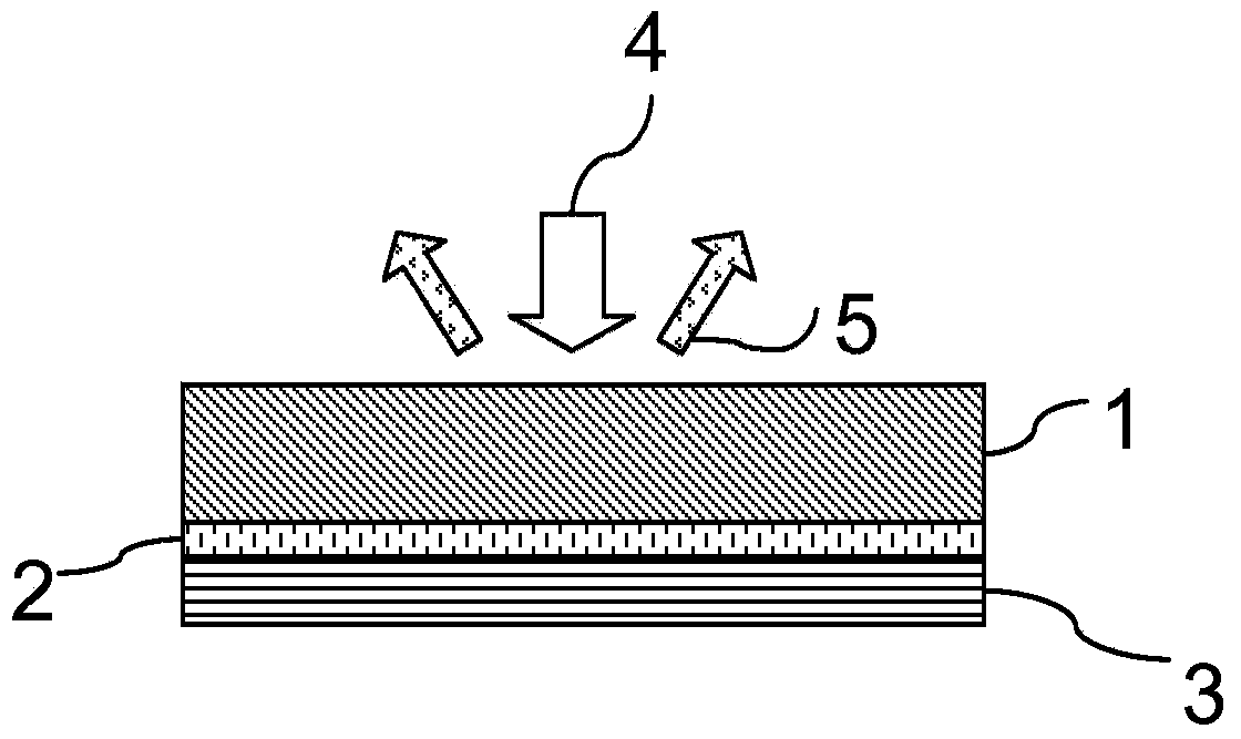
[0082] As a first example, figure 1 A side view showing the schematic structure of a diffusely operating converter.

[0083] The converter comprises a converter body 1 designed as an opto-ceramic and a mirror 3 , which are connected to one another via an adhesive layer 2 . The converter material (optoceramic) is a doped YAG ceramic or LuAG ceramic and forms a grain structure with strong scattering.

[0084] From above, i.e. from the excitation side, blue excitation light 4 of high power density (i.e. with a small beam cross section) falls onto the excitation side of the converter body 1 and, after entering the optoceramic, is converted to produce a long wavelength light 5 and is output outwards by scattering, as shown by the arrows.

[0085] The adhesive layer 2 has, for example, a thickness d of 10 μm Kleb . The mirror 3 reflects the excitation light 4 into the opto...


PUM

PropertyMeasurementUnit
luminanceaaaaaaaaaa
thicknessaaaaaaaaaa
quantum efficiencyaaaaaaaaaa

Abstract

The invention relates to an optical converter for producing colored or white light from blue excitation light (4). In addition to good conversion, the converter also has good scattering properties in order to be able to produce nearly white light from the scattered blue light components and the scattered, converted yellow light components (5). The converter material is a YAG ceramic or LuAG ceramic or a magnesium-aluminum ceramic having strong scattering.

Description

technical field [0001] The invention relates to a light converter for the generation of colored or white light, in which short-wavelength excitation light is converted by a converter medium into converted light with a longer wavelength. Background technique [0002] The long-wavelength excitation light is converted into diffusely reflected light with a longer wavelength by absorption and emission processes in the converter material. [0003] Within the meaning of the present invention, a converter is understood to be a part of a device for light conversion in which the conversion takes place. The converter here consists of a converter material. The converter material contains a luminescent material which, as a photoactive medium, brings about the conversion. The converter material can have differently sized phosphor densities. The expression “phosphor density” relates to the distribution of the phosphor or phosphor particles in the converter material. Thus, the luminesce...

Claims


Application Information

Patent Timeline
Patent Type & Authority Applications(China)
IPC IPC(8): C09K11/77C04B35/115C04B35/44C04B35/443F21V9/40
CPCC04B2235/3225F21V9/16C09K11/646C09K11/7774Y02B20/181C04B2235/763C04B2235/3286F21V13/08C04B2235/3224C09K11/7721C09K11/7706C04B35/44C04B2235/9653F21V9/30F21V9/45Y02B20/00C09K11/77214
Inventor 沃尔克·哈格曼彼得·纳斯伊冯娜·门克贝恩特·霍佩沃尔弗拉姆·拜尔赖纳·利巴尔德尼古·舒尔茨京特·魏德曼豪克·埃塞曼
Owner SCHOTT AG
Why Eureka
Try Eureka