Energy management device and system

An energy management and energy technology, applied in transmission systems, signal transmission systems, data processing applications, etc., can solve problems that cannot meet the needs of multiple energy scheduling

Inactive Publication Date: 2014-08-13
刘玮
View PDF10 Cites 49 Cited by
  • Summary
  • Abstract
  • Description
  • Claims
  • Application Information

AI Technical Summary

Problems solved by technology

[0006] However, the above-mentioned U-EMS only collects and analyzes the user's electric energy information,

Method used


Image

  • Energy management device and system
  • Energy management device and system
  • Energy management device and system

Examples


Embodiment 1

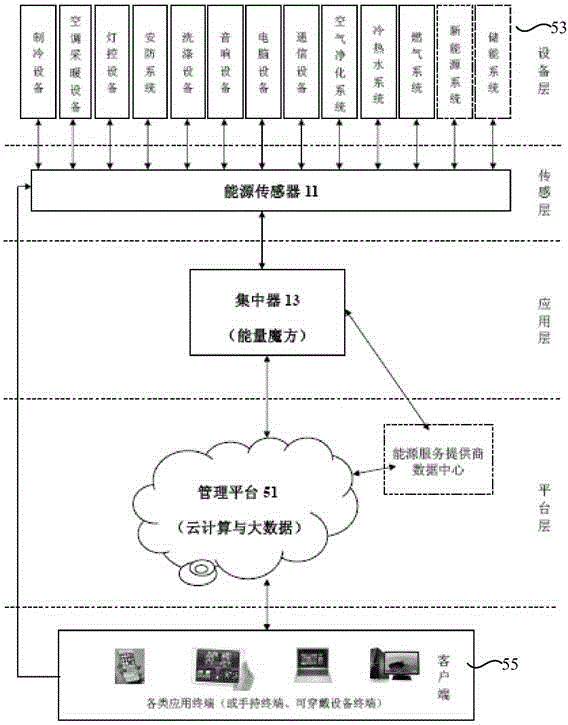
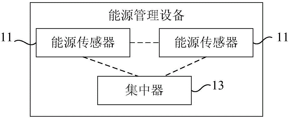
[0091] figure 1 It is a structural block diagram of an energy management device in Embodiment 1 of the present invention, such as figure 1 As shown, the energy management equipment may include:

[0092] At least two energy sensors 11 are respectively connected to at least two energy terminals on the user side, and are used to collect energy data of the energy terminals in time series, wherein the energy terminals include electric energy equipment, water body equipment and gas equipment. at least two;

[0093] The concentrator 13 is connected to each of the energy sensors 11, and is used to analyze based on the energy data, combined with the rated parameters and service data of each of the energy terminals, to determine the working conditions of each of the energy terminals, and based on the The determined working condition sends a scheduling instruction to each of the energy sensors 11, so that each of the energy sensors 11 can control the working status of each of the ene...

Embodiment 2

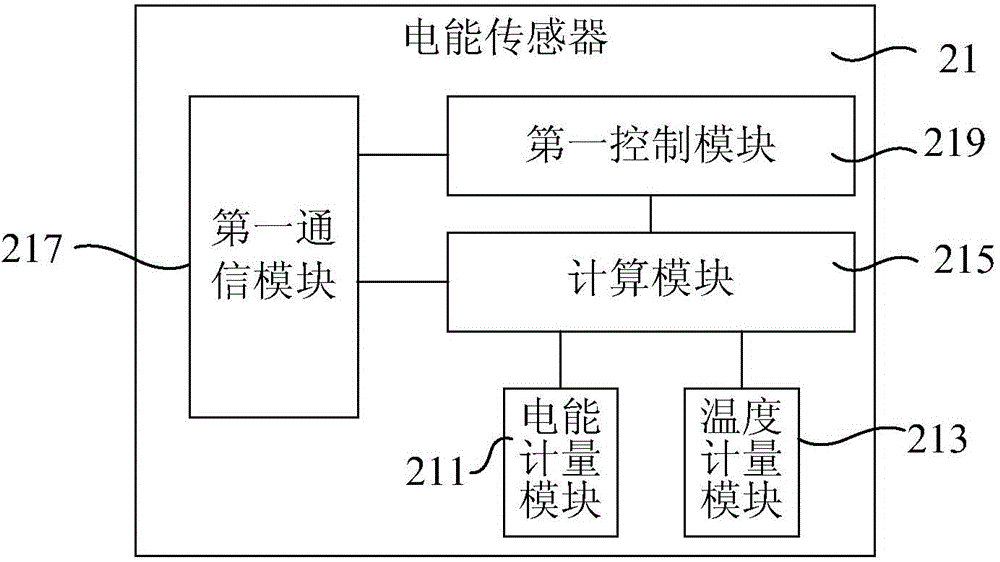
[0099] Figure 2a It is a structural block diagram of the electric energy sensor of the energy management device in Embodiment 2 of the present invention, such as Figure 2a As shown, on the basis of the above embodiments, the energy sensor of the energy management device in this embodiment may include an electric energy sensor 21, and the electric energy sensor 21 may include:

[0100] An electric energy metering module 211, configured to collect the instantaneous voltage and current of the electric energy equipment connected to the electric energy sensor according to time series;

[0101] A temperature measurement module 213, configured to detect the line temperature of the electric energy equipment connected to the electric energy sensor in time series;

[0102] A calculation module 215, configured to calculate at least one of apparent power, active power, reactive power, active fundamental wave, harmonic power, reactive fundamental wave power, power factor, and frequency ...

Embodiment 3

[0108] Figure 3a It is a schematic diagram of the water body sensor of the energy management device in Embodiment 3 of the present invention, as shown in Figure 3a As shown, on the basis of the above embodiments, the energy sensor of the energy management device in this embodiment may include a water body sensor 31, and the water body sensor 31 may include:

[0109] The first flow measurement module 311 is used to collect the instantaneous water volume and water pressure of the water equipment connected to the water sensor according to time series;

[0110] The first amplification module 313 is connected to the first flow metering module and is used to amplify the water volume and water pressure;

[0111] The first medium parameter measurement module 315 is configured to collect water quality parameter data and / or water temperature of the water equipment connected to the water sensor in time series;

[0112] The second communication module 317 communicates with the concent...


PUM


Abstract

The invention relates to an energy management device and system. The energy management device comprises at least two energy sensors and a concentrator, wherein the energy sensors are connected with at least two energy terminals on a user side respectively and used for collecting energy data of the energy terminals according to a time series; the concentrator is connected with the energy sensors and used for conducting analysis through combination with rated parameters and service data of the energy terminals on the basis of the energy data so as to determine the working conditions of the energy terminals and transmitting scheduling instructions to the energy sensors according to the determined working conditions so as to enable the energy sensors to be capable of responding to the scheduling instructions and controlling the working conditions of the energy terminals. The energy data, collected by various types of energy sensors, of various types of energy terminals can be gathered and analyzed comprehensively through the concentrator, so that the energy use condition of the user side is analyzed more accurately, and the requirements of users for energy scheduling on the condition that various kinds of energy are used can be met.

Description

technical field [0001] The invention relates to the field of energy management, in particular to an energy management device and system. Background technique [0002] Under the background of actively carrying out energy conservation, emission reduction and environmental protection, new energy and renewable energy are developing rapidly. Therefore, the energy consumed by users not only includes electricity from the grid, water from the water company, and natural gas from the gas company, but also includes user-owned production equipment, such as electricity produced by photovoltaic or wind power plants, or from user-provided energy storage. equipment power, etc. In other words, users are no longer a single energy consumption center, but gradually become energy interactors with dual identities of energy production center and energy consumption center. [0003] In recent years, due to the huge demand for energy saving, emission reduction and safety on the user side, the Unite...

Claims


Application Information

Patent Timeline
IPC IPC(8): G05B19/418G08C17/02H04L29/06G06Q50/06
CPCY02P90/02
Inventor 刘玮
Owner 刘玮
Why Eureka
Try Eureka