Piston pump for a high-pressure cleaning device

A high-pressure cleaning, piston pump technology, applied to components of pumping devices for elastic fluids, cleaning methods using liquids, mechanical equipment, etc., can solve the problem of limiting casing productivity, increasing piston pump manufacturing costs, and long cooling processes. And other issues

Active Publication Date: 2014-08-20
ALFRED KARCHER GMBH & CO KG
View PDF8 Cites 0 Cited by
  • Summary
  • Abstract
  • Description
  • Claims
  • Application Information

AI Technical Summary

Problems solved by technology

This situation is associated with considerable manufacturing costs
Furthermore, the relatively high material strength has the consequence that the housings of the piston pumps, which are usually cast, are subjected to long cooling processes during production, which limit the production rate of the housings.
This manufacturing method also increases the manufacturing cost of the piston pump

Method used


Image

  • Piston pump for a high-pressure cleaning device
  • Piston pump for a high-pressure cleaning device
  • Piston pump for a high-pressure cleaning device

Examples


Embodiment Construction

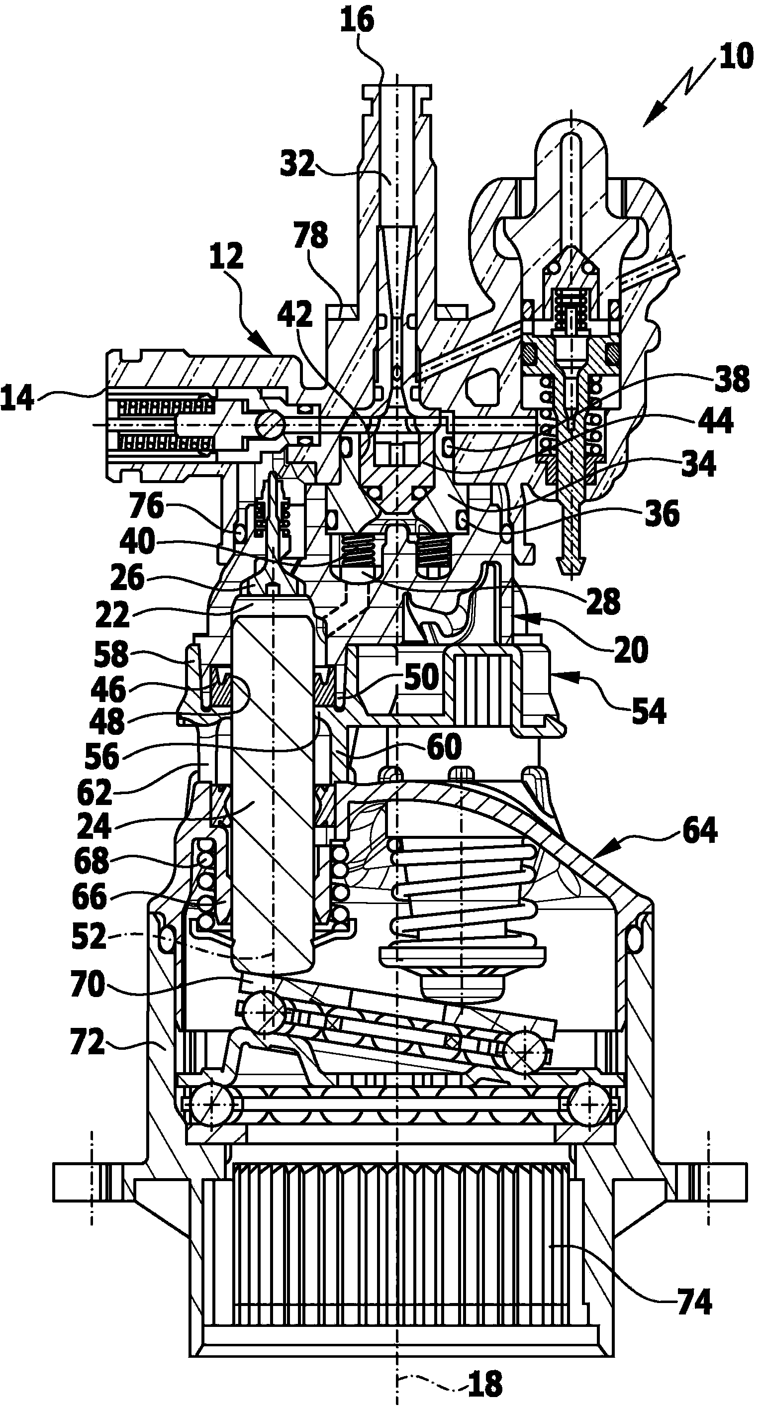
[0026] An advantageous embodiment of the piston pump according to the invention, which is designated as a whole by the reference numeral 10 , is shown schematically in the drawing. The piston pump 10 comprises a pump head 12 with a suction inlet 14 via which a fluid to be pressurized, preferably water, can be delivered to the piston pump 10 . For example, a supply line can be connected to the suction inlet 14 . Furthermore, the pump head 12 has a pressure outlet 16 via which pressurized liquid can be discharged. For example, a pressure hose can be connected to the pressure outlet 16 , which pressure hose carries at its free end a discharge device for the pressurized liquid, for example a spray gun or a nozzle.

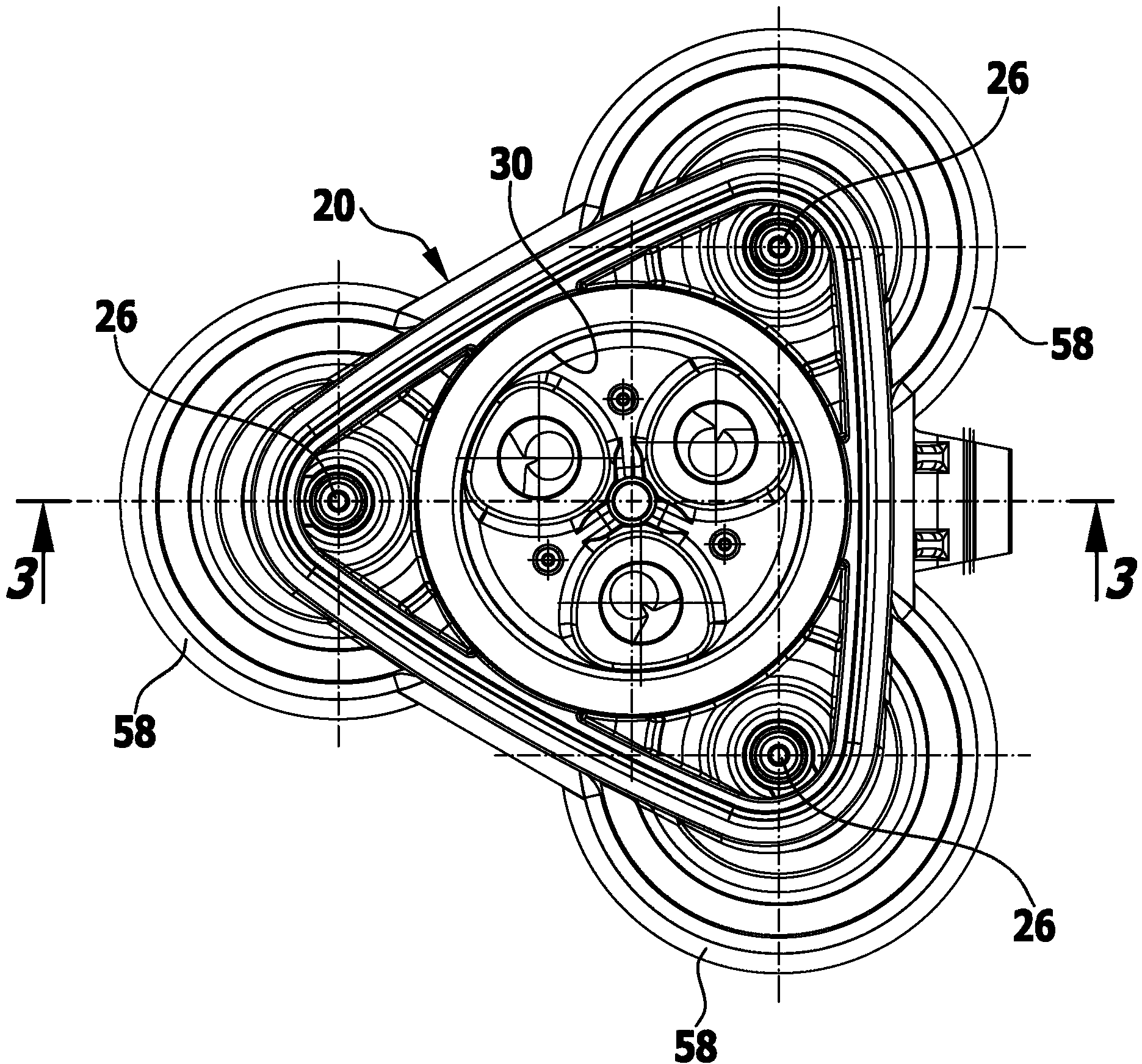
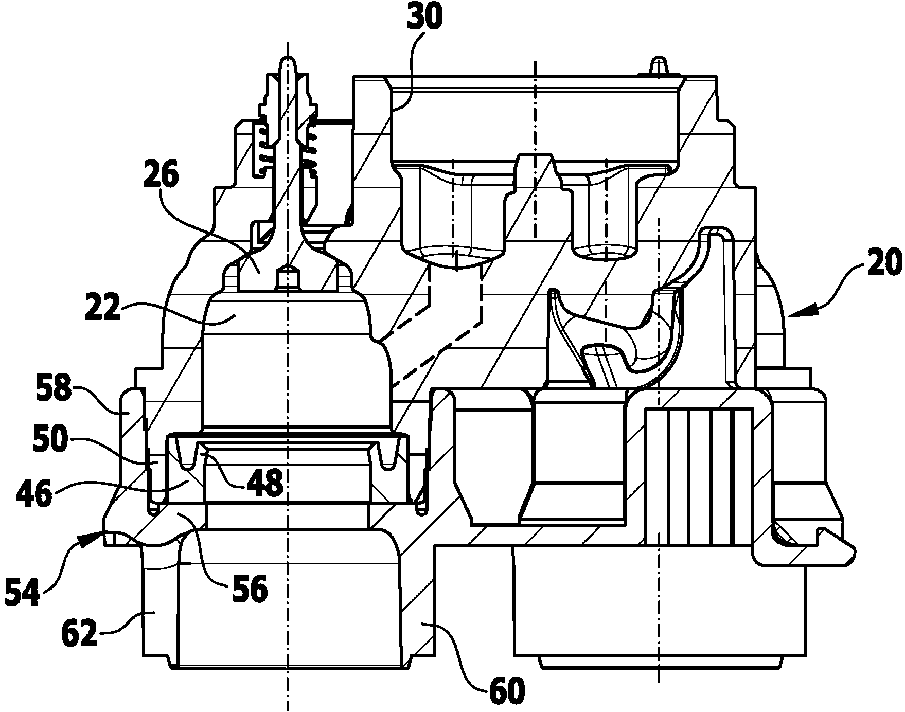
[0027] The pump head 12 is arranged in an axial direction based on the pump longitudinal axis 18 on a pump body 20 which has a plurality of pump chambers 22 into which pistons 24 each protrude. The piston pump 10 illustrated in the drawing has overall three pump cham...


PUM


Abstract

The invention relates to a piston pump (10) for a high-pressure cleaning device, having a plurality of pump chambers (22), into which in each case one piston (24) which can move to and fro dips and which are flow-connected in each case via an upstroke valve (26) to a suction inlet (14) and via a delivery valve (28) to a pressure outlet (16), wherein the pistons (24) are surrounded in each case by a seal ring (46) which is supported in the radial direction by a ring wall (50) and in the axial direction by a supporting ring (56). In order to develop the piston pump in such a way that it can be produced and assembled less expensively, it is proposed according to the invention that the piston pump (10) comprises a single-piece supporting plate (54) which forms the supporting rings (56) and surrounds the ring walls (50) in the circumferential direction.

Description

technical field [0001] The invention relates to a piston pump for high-pressure cleaning equipment, which has a plurality of pump chambers, into which the reciprocating pistons respectively protrude, and the pump chambers respectively pass through a suction valve and a suction inlet and through a pressure valve. Establish fluid connection with pressure outlet In this case, the pistons are each surrounded by a sealing ring which is supported in the radial direction by the annular wall and in the axial direction by the support ring. Background technique [0002] With a piston pump of this type, a liquid, preferably water, can be pressurized and directed at the object or surface to be cleaned. For this purpose, for example, the piston can be driven by means of a swash plate for a reciprocating movement, so that the volume of the pump chamber is periodically changed, while the liquid is sucked from the suction inlet via the suction valve into the pump chamber, where Pressuriz...

Claims


Application Information

Patent Timeline
Patent Type & Authority Applications(China)
IPC IPC(8): F04B1/14F04B53/02F04B53/16B08B3/02
CPCF04B53/164F04B53/02F04B1/143F04B1/2078
Inventor 罗伯特·内森
Owner ALFRED KARCHER GMBH & CO KG
Why Eureka
Try Eureka