Series connection type unilateral elliptic function transmission line filter

An elliptic function and transmission line technology, applied in the field of filters, can solve the problems of difficult to meet practical application requirements, increased in-band group delay fluctuation, difficult processing and debugging, etc., to achieve easy design and implementation, excellent high frequency Performance, easy to process effects

Active Publication Date: 2014-10-01
10TH RES INST OF CETC
View PDF4 Cites 2 Cited by
  • Summary
  • Abstract
  • Description
  • Claims
  • Application Information

AI Technical Summary

Problems solved by technology

However, the circuit implementation is complicated, and it is usually implemented by introducing cross-coupling between non-adjacent resonant cavities.
Although the synthesis and design of this filter with cross-coupling have been widely studied, its processing and debugging are difficult, which limits its engineering application.
[0004] In order to achieve good frequency selection characteristics near the working frequency band, band-pass filters and band-stop filters are mainly used at present. However, band-pass filters with steep transition band attenuation characteristics generally require multi-stage filters. Multi-stage filters are composed of a Composed of a series of mutually coupled resonators, the insertion loss is large, the in-band group delay and its fluctuation increase, and the volume is large
Multi-stage band-stop filters have the same disadvantages
A filter with a single high-Q resonant tank can achieve lower insertion loss, but this single-loop filter has a narrow bandwidth, which is difficult to meet the requirements of practical applications

Method used


Image

  • Series connection type unilateral elliptic function transmission line filter
  • Series connection type unilateral elliptic function transmission line filter

Examples


Embodiment Construction

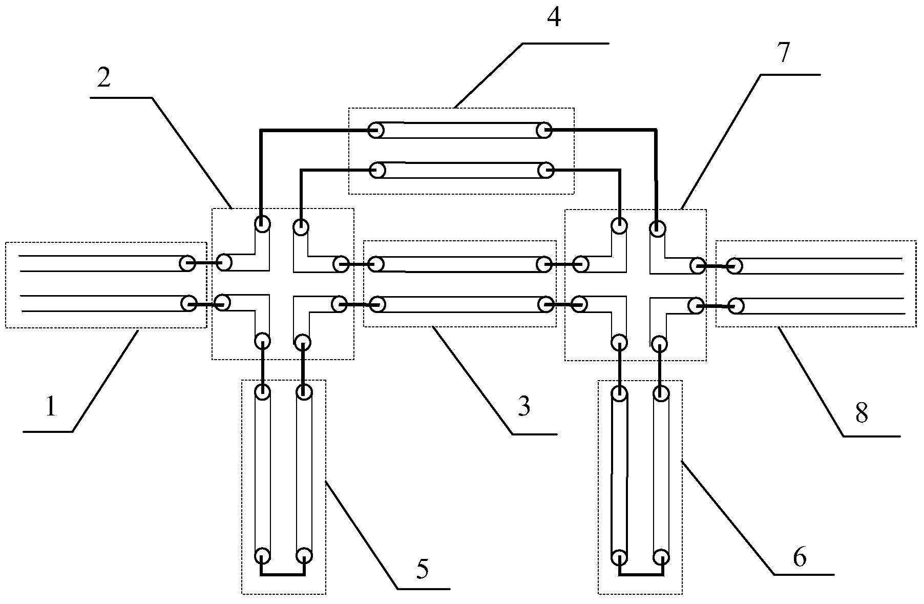
[0017] refer to figure 1 . In the embodiment described below, the series-type single-sided elliptic function transmission line filter is composed of six basic transmission line elements, including input and output transmission lines, series cross joints, short-circuited transmission line stubs, cascaded transmission line sections, and series transmission line sections. figure 1 Each transmission line in the above is expressed in the form of a double line. The specific circuit implementation can adopt various high-frequency transmission line forms including double-conductor transmission lines. The transmission line components are all in the form of various high-frequency transmission lines including parallel double lines. The series cross joint is a four-port transmission line element, and its function is to realize the series connection of any four transmission lines of the same type; The transmission line elements form a distributed parameter network, wherein the first serie...


PUM


Abstract

The invention provides a series connection type unilateral elliptic function transmission line filter. A distributed parameter network is composed of an input transmission line, an output transmission line, series connection cross joints, short circuit transmission line branch joints, a cascading transmission line joint, a series connection transmission line joint and other transmission line elements. The first series connection cross joint (2) and the second series connection cross joint (7) are arranged oppositely, opposite ports of the first series connection cross joint (2) and the second series connection cross joint (7) are connected through the cascading transmission line joint (3), ports in the same sides of the series connection cross joint (2) and the second series connection cross joint (7) are connected through the series connection transmission line joint (4), another two ports of the first series connection cross joint (2) are connected with the input transmission line (1) and the first short circuit transmission line branch joint (5) respectively, and another two ports of the second series connection cross joint (7) are connected with the output transmission line (8) and the second short circuit transmission line branch joint (6) respectively. All transmission line element parameters in the filter are appropriately designed, so that transmission characteristics of a unilateral elliptic function are achieved. The filter is suitable for bandwidths below the medium degree of microwave and millimeter wave frequency bands, low in loss, and high in selectivity.

Description

technical field [0001] The invention relates to a system widely used in microwave and millimeter wave frequency band communication, radar and measuring instruments, etc., to control the frequency response of signals, block the transmission of frequency components of useless signals, and make the frequency components of useful signals pass through almost without attenuation filter. Background technique [0002] Filters are passive circuits widely used in microwave circuits and systems. They are used to achieve specific frequency selection characteristics. Filters can be divided into high-pass, low-pass, band-pass and band-rejection types according to transmission characteristics. The passband of the filter Properties such as insertion loss and stop band rejection have a great influence on the performance index of the circuit. With the increasingly tight frequency resources and the increasingly crowded spectrum, the radio system puts forward higher requirements for the freque...

Claims


Application Information

Patent Timeline
Patent Type & Authority Applications(China)
IPC IPC(8): H01P1/20H01P1/203
Inventor 黄建
Owner 10TH RES INST OF CETC
Why Eureka
Try Eureka