Transformer

A technology of transformers and electrodes, applied in the field of transformers, can solve the problems of shortening the interval distance, ignition, short-circuiting, etc., and achieve the effects of increasing the magnetic permeability, increasing the withstand voltage strength, and reducing the probability of deformation

Inactive Publication Date: 2014-10-15
DELTA ELECTRONICS INC
View PDF5 Cites 0 Cited by
  • Summary
  • Abstract
  • Description
  • Claims
  • Application Information

AI Technical Summary

Problems solved by technology

However, in the process of gradually reducing the size of the transformer, many technical bottlenecks are often encountered
For example, when the size of the transformer is getting smaller and smaller, when the primary winding group and the secondary winding group are connected with high voltage, due to the shortened distance between them, it is easy to spark and cause a short circuit. When this kind of problem occurs, it is usually necessary to increase the length of the iron core around which each coil group is wound, but while increasing the length, it will run counter to the goal of reducing the volume

Method used


Image

  • Transformer
  • Transformer
  • Transformer

Examples


Embodiment Construction

[0038] A transformer according to a preferred embodiment of the present invention will be described below with reference to related drawings, wherein the same components will be described with the same reference symbols. It should be noted that the illustrations are for illustration only, and do not represent actual dimensions and ratios, which can be designed in different ways according to actual needs.

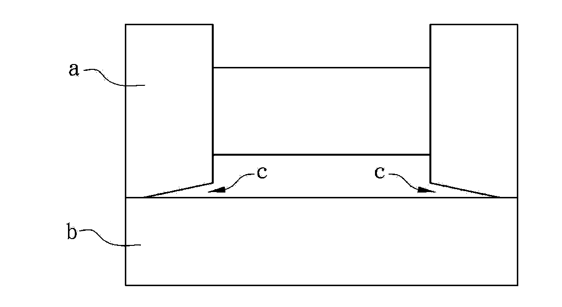
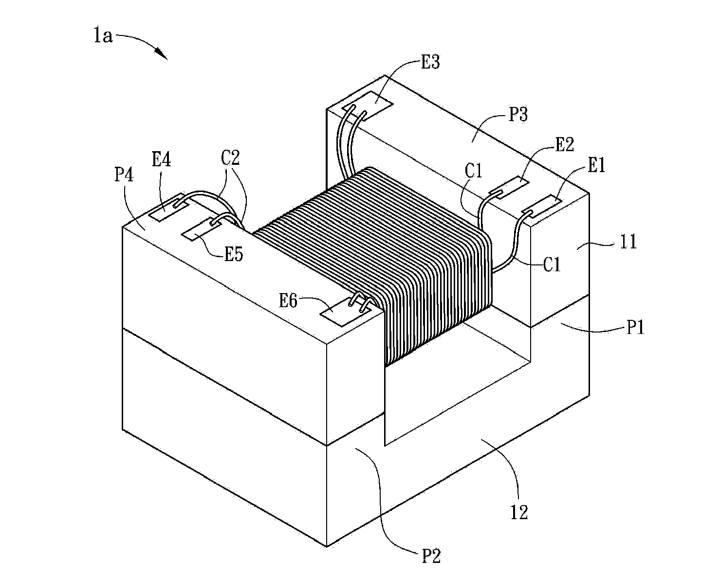
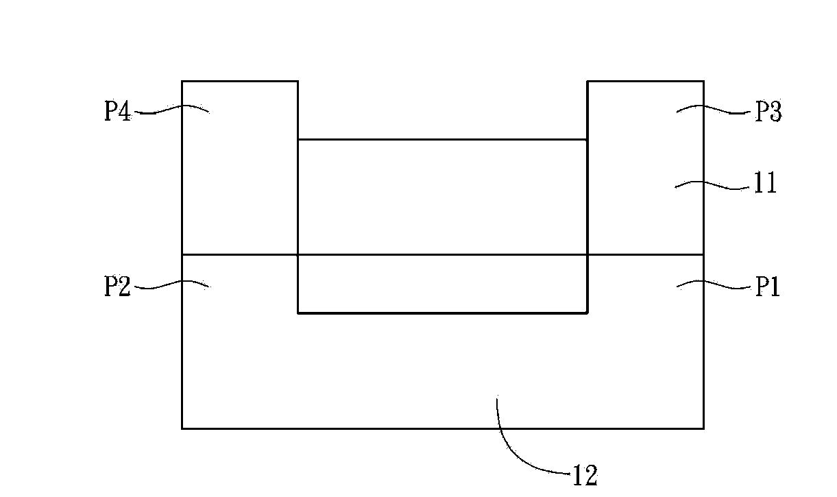
[0039] Please refer to figure 2 As shown, it is a schematic diagram of a transformer 1 according to a preferred embodiment of the present invention. Please also refer to Figure 3A and Figure 3B Shown to facilitate understanding, where Figure 3A It is a side view of the first magnetic permeable element 11 and the second magnetic permeable element 12, Figure 3B It is a top view of the first magnetic permeable element 11 . The transformer 1 includes a first magnetically conductive element 11 , a primary winding C1 , a secondary winding C2 and a second magnetically con...


PUM


Abstract

The invention discloses a transformer, which comprises a first magnetic conduction element, a primary winding and a second magnetic conduction element, wherein the primary winding is arranged around the first magnetic conduction element, a secondary winding is arranged around the first magnetic conduction element, the second magnetic conduction element comprises a first flange and a second flange, the first flange is arranged at one end of the second magnetic conduction element, the second flange is arranged at the other end of the second magnetic conduction element, the first flange and the second flange are connected with the first magnetic conduction element, and in addition, the magnetic conductivity of the second magnetic conduction element is greater than the magnetic conductivity of the first magnetic conduction element.

Description

technical field [0001] The present invention relates to a transformer. Background technique [0002] A transformer (transformer) is an electronic device that applies Faraday's law of electromagnetic induction to increase or decrease voltage. It is mainly used to increase or decrease the voltage of alternating current or change impedance or separate circuits. [0003] Please refer to figure 1 As shown, it is a schematic diagram of the connection between the first magnetically permeable element a and the second magnetically permeable element b used by the transformer to wind the winding group in the prior art, as shown in figure 1 As shown, due to the relationship between the structural shape of the first magnetic permeable element a and the second magnetic permeable element b, during the sintering process, the position where the first magnetic permeable element a is connected to the second magnetic permeable element b will naturally form an air gap c , and because the magne...

Claims


Application Information

Patent Timeline
IPC IPC(8): H01F27/24H01F27/29H01F27/30
Inventor 戴进忠
Owner DELTA ELECTRONICS INC
Why Eureka
Try Eureka