A riveting machine

A riveting machine and pliers technology applied in the field of riveting machines to achieve the effects of fewer parts, flexible rotation, and cost-saving manufacturing

Active Publication Date: 2016-05-11
CRRC QIQIHAR ROLLING CO LTD
View PDF5 Cites 0 Cited by
  • Summary
  • Abstract
  • Description
  • Claims
  • Application Information

AI Technical Summary

Problems solved by technology

This riveting machine can effectively solve the problems of existing riveting machines in terms of structure, product adaptability, safety and reliability, etc., and significantly reduce labor intensity and improve production efficiency

Method used


Image

  • A riveting machine
  • A riveting machine
  • A riveting machine

Examples


Embodiment Construction

[0059] In order to enable those skilled in the art to better understand the solution of the present invention, the present invention will be further described in detail below in conjunction with the accompanying drawings and specific embodiments.

[0060] The explanations in the description of the present invention are limited to the implementation of exemplary solutions, and descriptions of unnecessary components are omitted. In the description of the present invention, the same components are represented by the same symbols in different drawings. In specific implementation descriptions, numbers and letters are used to distinguish component elements with the same term, and these numbers and letters do not have specific meanings, nor do they represent any sequence.

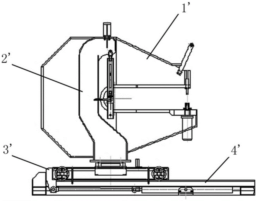
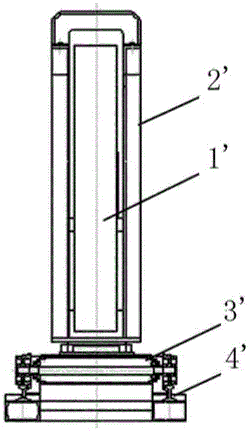
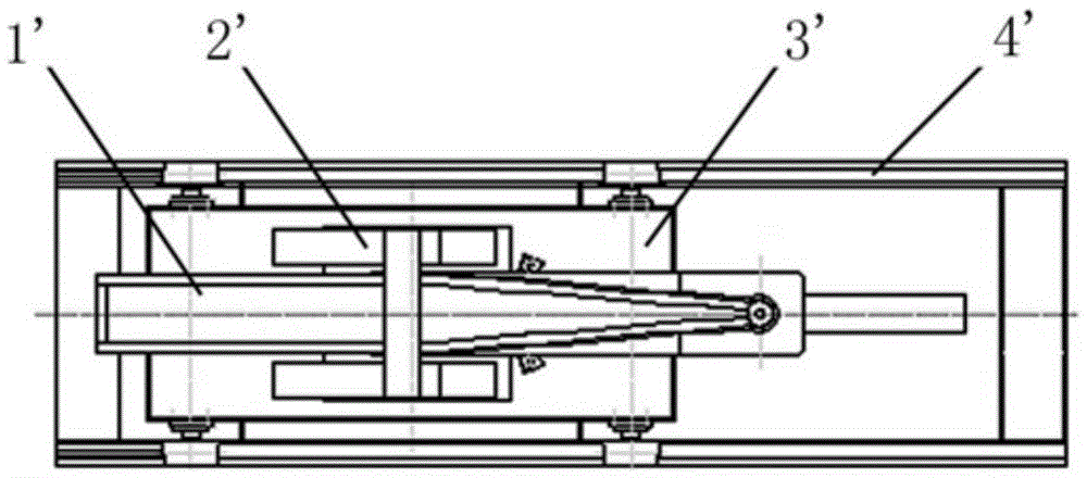
[0061] Please refer to Figure 4 , Figure 5 , Figure 4 It is a structural schematic diagram of a riveting machine provided by the present invention; Figure 5 for Figure 4 left view of .

[0062] In a specif...


PUM

PropertyMeasurementUnit
depthaaaaaaaaaa
depthaaaaaaaaaa

Abstract

The invention discloses a riveting machine which comprises a pincer trolley, a rotating support and a pincer body. The pincer trolley is provided with wheels and can move horizontally on a track. The rotating support is arranged on the pincer trolley in a rotatable mode. The pincer body is hung between the rotating support and a stand plate. Rotating shafts are arranged on the two sides of the pincer body which is directly hung on the stand plate through the rotating shafts. The hanging hinging point is placed at the position above the gravity center. The stand plate supports the rotating shafts to form the hanging hinging point through an opening type semicircular hole formed in the stand plate. The riveting machine can effectively solve the problems existing in the structure, the product applicability, the safety, the reliability and the like of an existing riveting machine, labor intensity is effectively lowered, and production efficiency is improved.

Description

technical field [0001] The invention relates to the technical field of mechanical assembly equipment, in particular to a riveting machine for riveting the side walls and end walls of a car body during the production of aluminum alloy coal cars. Background technique [0002] At present, the production of aluminum alloy coal cars mainly uses riveting guns to rivet Hack rivets, and some rivet machines are used to rivet aluminum rivets for assembly. [0003] Due to the large amount of Huck rivets, the cost is high and the productivity is low. Therefore, it is a practical solution to replace Huck rivets with aluminum rivets. CCI type aluminum rivets can be used on the end and side walls. [0004] Please refer to figure 1 , figure 2 , image 3 , figure 1 It is a structural schematic diagram of the existing CCI type aluminum rivet machine; figure 2 for figure 1 left view of image 3 for figure 1 top view. [0005] As shown in the figure, the existing CCI aluminum riveti...

Claims


Application Information

Patent Timeline
Patent Type & Authority Patents(China)
IPC IPC(8): B21J15/14B21J15/20B21J15/30
Inventor 潘洪流刘正斌杨焕春张军凤宫文新赵宪鑫
Owner CRRC QIQIHAR ROLLING CO LTD
Why Eureka
Try Eureka