A Fault Diagnosis Method for Rolling Bearings Based on Vibration Time-Frequency Analysis

A rolling bearing and fault diagnosis technology, which is applied in mechanical bearing testing and other directions, can solve the problems of complex vibration signals, unsuitable rolling bearing online diagnosis, and no clear standard for fault feature extraction, etc., and achieve the effect of fast and accurate identification

Active Publication Date: 2017-07-07
TIANJIN UNIV
View PDF6 Cites 0 Cited by
  • Summary
  • Abstract
  • Description
  • Claims
  • Application Information

AI Technical Summary

Problems solved by technology

However, due to the more complex vibration signals of rolling bearings, it is still necessary to optimize the smoothing method and end-point effects if the inherent time scale decomposition is used for the analysis of vibration signals of rolling bearing faults.
[0004] In addition, there is no clear standard for fault feature extraction. In order to meet the requirements of fault diagnosis accuracy, it is usually necessary to extract multiple fault features, which greatly increases the amount of calculation. At the same time, as the number of features increases, the redundancy between features will limit fault diagnosis. Further improvement in accuracy
In terms of failure mode recognition, conventional methods such as neural network, support vector machine and other models are relatively complex, and have high requirements for the professional knowledge of users, which are not suitable for online diagnosis of rolling bearings.

Method used


Image

  • A Fault Diagnosis Method for Rolling Bearings Based on Vibration Time-Frequency Analysis
  • A Fault Diagnosis Method for Rolling Bearings Based on Vibration Time-Frequency Analysis
  • A Fault Diagnosis Method for Rolling Bearings Based on Vibration Time-Frequency Analysis

Examples


Embodiment Construction

[0027] A method for diagnosing rolling bearing faults based on vibration time-frequency analysis of the present invention will be described in detail below in conjunction with embodiments and drawings.

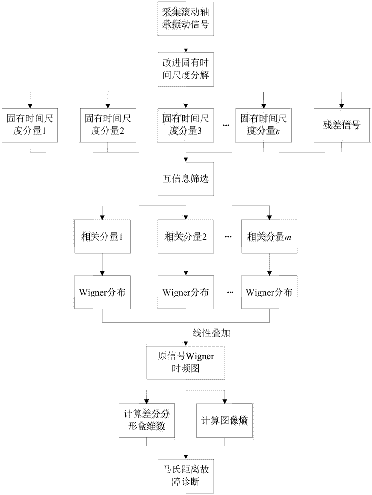
[0028] A rolling bearing fault diagnosis method based on vibration time-frequency analysis of the present invention, such as figure 1 shown, including the following steps:

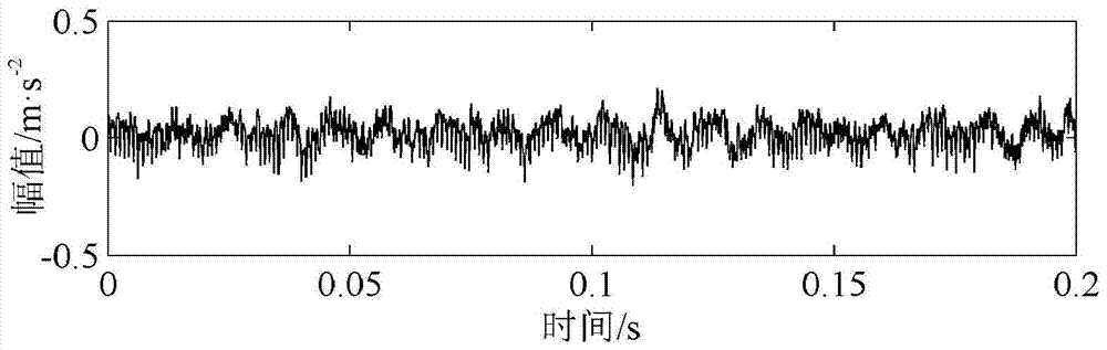
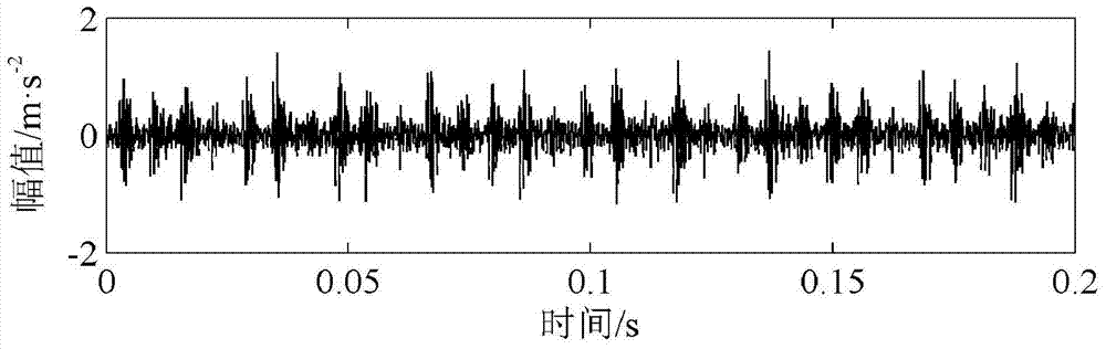
[0029] (1) Use the vibration acceleration sensor to collect the vibration signals of the rolling bearing under normal conditions and fault conditions;

[0030] (2) Improve the interpolation method and endpoint effect processing method in the intrinsic time scale decomposition, and use the improved intrinsic time scale decomposition method to decompose the collected vibration signal x(t) to generate several intrinsic time scales Component HF m (t) and the residual signal u n (t):

[0031]

[0032] Wherein, the interpolation method in the improved inherent time scale decomposition is to use piecewise ...


PUM


Abstract

The invention discloses a rolling bearing failure diagnosis method base on vibration temporal frequency analysis. The method comprises the following steps: utilizing a vibration acceleration sensor to collect vibration signals of the rolling bearing under a normal condition and a failure condition; utilizing a modified inherent time scale resolving method to resolve the collected vibration signals, and generating a plurality of inherent time scale components and residual signals; calculating relativity of the time scale components and the vibration signals, selecting the inherent time scale components of which the relativity is ranked top 5 as related components, and rejecting noise signals and false components; calculating Wigner distribution of the related components respectively, and conducting linear stack to obtain the Wigner temporal frequency figure of the original signal; extracting difference fractal box dimensionality of the Wigner temporal frequency figure and the image entropy as failure characteristics; utilizing mahalanobis distance to build mapping relation of the failure characteristics and failure types to realize failure diagnosis. According to the invention, interference of Wigner distribution cross terms is avoided; two kinds of representative failure characteristics of the difference fractal box dimensionality and the image entropy are confirmed.

Description

technical field [0001] The invention relates to a rolling bearing fault diagnosis method. In particular, it relates to a rolling bearing fault diagnosis method based on vibration time-frequency analysis. Background technique [0002] Vibration analysis is the simplest and most direct method for fault diagnosis of rolling bearings. Vibration analysis methods can be divided into time-domain analysis, frequency-domain analysis and time-frequency analysis. Among them, the time-frequency analysis method has always been a research hotspot because it can comprehensively reflect the changes of vibration signals with time and frequency. The Wigner distribution is a typical time-frequency analysis method, which has good time-frequency aggregation and can reflect the essential characteristics of vibration signals, but it is only suitable for processing single-component signals. When measuring signals, the generated Wigner time-frequency diagram will be inaccurate due to the interfere...

Claims


Application Information

Patent Timeline
Patent Type & Authority Patents(China)
IPC IPC(8): G01M13/04
Inventor 张俊红刘昱林杰威马梁马文朋
Owner TIANJIN UNIV
Why Eureka
Try Eureka