Method and device for fault diagnosis of rotor system based on vibration analysis

A technology of system faults and diagnostic methods, applied in the direction of measuring devices, testing of mechanical components, testing of machine/structural components, etc., can solve problems such as modal confusion, over-envelope, and wavelet basis function selection without clear standards, etc. Achieve rapid and accurate identification and alleviate the effect of error accumulation

Active Publication Date: 2017-03-22
TIANJIN UNIV
View PDF5 Cites 0 Cited by
  • Summary
  • Abstract
  • Description
  • Claims
  • Application Information

AI Technical Summary

Problems solved by technology

[0002] Vibration analysis is the simplest and most direct method for fault diagnosis of the rotor system. Typical vibration analysis methods include: short-time Fourier transform, wavelet transform, empirical mode decomposition, etc., but they all have their own limitations: short-time Fourier transform is only suitable for dealing with stationary signals, and cannot take into account the requirements of frequency and time resolution; although wavelet transform has a variable time-frequency window, there is no clear standard for the selection of wavelet basis functions; empirical mode decomposition is a An adaptive time-frequency decomposition method has been widely used in rotating machinery fault diagnosis, but this method has over-envelope, modal confusion, end effect and unexplainable negative frequency caused by Hilbert transform, etc. question
Among them, the directed acyclic method is more efficient and there is no inseparable area, but because the distribution of directed acyclic nodes is random, if the upper layer nodes are misclassified, the error will be transmitted to the lower layer nodes, which will eventually affect the accuracy of fault diagnosis, which is called Directed Acyclic Error Accumulation Phenomenon

Method used


Image

  • Method and device for fault diagnosis of rotor system based on vibration analysis
  • Method and device for fault diagnosis of rotor system based on vibration analysis
  • Method and device for fault diagnosis of rotor system based on vibration analysis

Examples


specific example

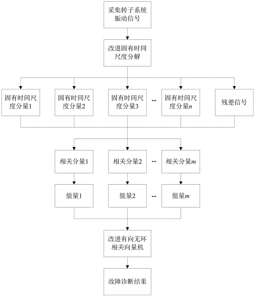
[0078] This example uses Figure 5 The experimental data of the rotor test bench shown is verified. The test bench is based on the low-pressure rotor system of the PW4000 twin-rotor turbofan engine, and adopts the same 0-2-1 support structure and bearing type as the original machine. The test bench size It is twice the size of the model and driven by a motor.

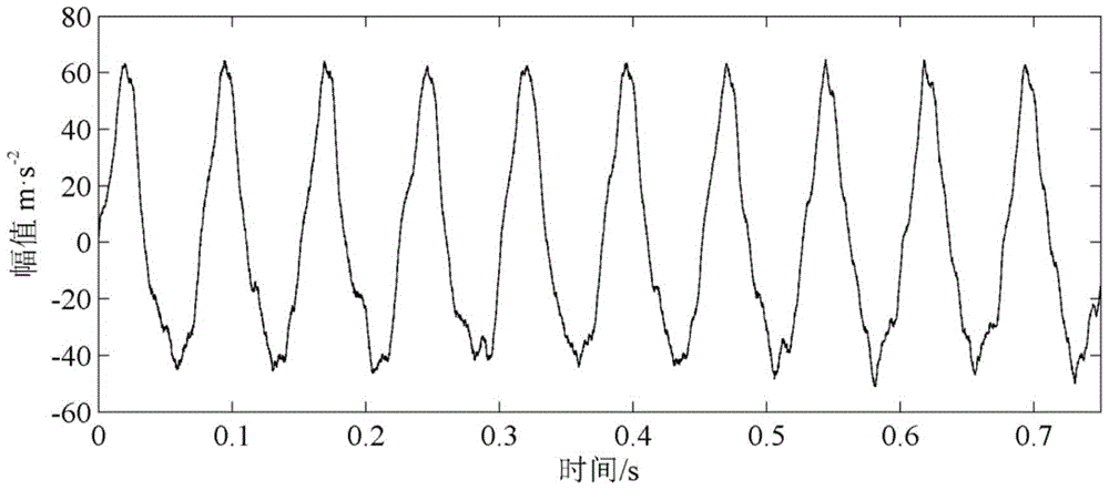
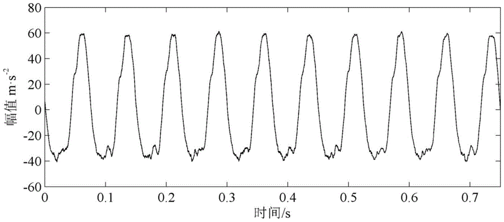
[0079] Step 1. Use the vibration displacement sensor to collect 20 sets of signals for normal, slight misalignment, severe misalignment, rubbing, and bearing rolling element faults of the rotor system. A total of 100 sets of signals are obtained. The sampling frequency is 20kHz, and the vibration signals of the five states of the rotor system are obtained. like Figure 2a , Figure 2b , Figure 2c , Figure 2d and Figure 2e shown. Among them, the misalignment fault is realized by adjusting the support height of the bearing seat, the rubbing fault is realized by the rubbing device, and the bearing fault is realize...


PUM


Abstract

The invention discloses a rotor system fault diagnosis method and device based on vibration analysis. A sensor acquires normal conditions of a rotor system and vibration signals under fault conditions; the acquired vibration signals are decomposed by an improved inherent time scale decomposition method to generate a plurality of rotational components and residual signals; related rotational components capable of reflecting fault information are selected from the rotational components; energy of each related rotational component is calculated; related vector machine multi-classification models are built by an improved directed acyclic method; fault characteristics are inputted to the related vector machine multi-classification models for training and fault diagnosis. A motor, a first bearing block, a second bearing block and a third bearing block are arranged on a test bed base, the first bearing block, the second bearing block and the third bearing block respectively support a first rotating shaft and a second rotating shaft which are sequentially connected with an output shaft of the motor, both the first rotating shaft and the second rotating shaft are provided with a disk, and a sensor group is arranged at the end of the second rotating shaft. Rotor system fault types can be rapidly and accurately recognized, and the method and the device are applicable to online diagnosis of the rotor system.

Description

technical field [0001] The invention relates to a fault diagnosis method for a rotor system. In particular, it relates to a vibration analysis-based fault diagnosis method and device for a rotor system. Background technique [0002] Vibration analysis is the simplest and most direct method for fault diagnosis of the rotor system. Typical vibration analysis methods include: short-time Fourier transform, wavelet transform, empirical mode decomposition, etc., but they all have their own limitations: short-time Fourier transform is only suitable for dealing with stationary signals, and cannot take into account the requirements of frequency and time resolution; although wavelet transform has a variable time-frequency window, there is no clear standard for the selection of wavelet basis functions; empirical mode decomposition is a An adaptive time-frequency decomposition method has been widely used in rotating machinery fault diagnosis, but this method has over-envelope, modal co...

Claims


Application Information

Patent Timeline
Patent Type & Authority Patents(China)
IPC IPC(8): G01M13/00
Inventor 张俊红刘昱林杰威马文明鲁鑫
Owner TIANJIN UNIV
Why Eureka
Try Eureka