Light beam remote signal receiver and equipment using same

A remote control signal and receiver technology, applied in the field of remote control systems, can solve the problems of affecting the size and appearance of electrical appliances, not being applicable, increasing the photosensitive area, etc.

Active Publication Date: 2014-11-19
嘉善陶庄再生资源有限公司
View PDF6 Cites 4 Cited by
  • Summary
  • Abstract
  • Description
  • Claims
  • Application Information

AI Technical Summary

Problems solved by technology

[0009] The announcement date applied by the inventor is February 6, 2008, and the application number is 200720018952.1. The laser remote control receiver auxiliary device named laser remote control receiver device scatters the laser light through the photosensitive cover, so that the laser light can easily irradiate the photosensitive On the element, thereby greatly increasing the photosensitive area, but the photosensitive cover described in this patent requires the photosensitive element to be located behind the photosensitive cover, and the laser remote control receiving device described in this patent is an auxiliary device for laser remote control receivers, It is not a complete receiver and needs to be used in combination with the existing laser remote control. However, due to the shortcomings of the existing laser remote control, it can only be better applied to simple remote control, such as the switch of remote control appliances, and the control of electrical appliances. Complicated remote control is not suitable, and a photosensitive cover with a larger area is required, which affects the volume and appearance of existing electrical appliances

Method used


Image

  • Light beam remote signal receiver and equipment using same
  • Light beam remote signal receiver and equipment using same
  • Light beam remote signal receiver and equipment using same

Examples


Embodiment 1

[0106] There are many kinds of remote control electric lights now, and the remote control electric lights include remote controllers, signal receivers, and electric lights.

[0107] The laser remote control signal transmitter is used as a remote control, and the beam remote control signal receiver is used as a signal receiver. For the structure of the astigmatism plate part of the beam remote control signal receiver, refer to the following Figure 4 .

[0108] The diffuser plate 41 is a fan-shaped flat box made of translucent plastic. The upper layer of the diffuser plate 41 mainly scatters the optical signal, and the lower layer diffusely reflects the optical signal.

[0109] The phototransistor 42 is located at the top of the fan-shaped diffuser 41 and at the back of the side of the diffuser 41 that is irradiated by the laser light. Since light signals are everywhere in the diffuser plate 41 after scattering and diffuse reflection, the direction of the photosensitive surf...

Embodiment 2

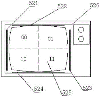
[0122] refer to Figure 5 , the light beam remote control signal receiver includes four filter channels 521, 522, 523, 524 and photosensitive transistors and diffuser plates installed inside. The diffuser plate 525 uses a TV screen.

[0123] Each filter channel has the same basic structure, take the filter channel 521 as an example, refer to Figure 6 To illustrate, the light transmission port of the filter channel 521 is equipped with a red glass 5212 to prevent dust from entering and to filter light, and a phototransistor with a photosensitive surface facing the red glass 5212 is installed in the filter channel 521 .

[0124] refer to Figure 5 , the filter channels 521, 522, 523, 524 are installed in the parts where the TV casing 526 is in contact with the outside of the TV screen 525, and are respectively located in the middle of the top, bottom, left, and right of the TV screen, and the photosensitive surface faces the diffuser plate 525 .

[0125] The signal processi...

Embodiment 3

[0148] refer to Figure 7 , the projector system has a projector 61 and a screen 62, and the light beam remote control signal receiver uses the screen 62 of the projector system as a diffuser.

[0149] refer to Figure 8 , the two optical components 612, 613 of the light beam remote control signal receiver are installed on the projector 61, and are respectively located at the left and right of the lens 611.

[0150] The working principle of the light beam remote control signal receiver applied to the projector system is the same as that of the light beam remote control signal receiver applied to the TV. The screen is divided into two parts by calculating the signal difference, and the action of the laser signal on the screen is used as the remote control signal information.

[0151] The laser remote control signal transmitter has at least two buttons, one button controls the laser to send out a non-controlled laser signal, which only serves as an indicator; one button contro...


PUM


Abstract

The invention discloses a light beam remote signal receiver and equipment using the light beam remote signal receiver and relates to a light signal receiving system, in particular to a light beam remote signal receiver and a laser remote signal emitter. As a light diffusion plate structure is adopted, the light beam remote signal receiver has the characteristics of large light-sensing area, low cost and no occupation of additional space; as a signal processing device capable of performing complex processing on a signal is adopted, the light beam remote signal receiver has the function of receiving a laser actuating signal; as a ring-shaped fixed structure is used, the laser remote signal emitter can be well matched with hands of people, and a variety of control signals are given by using gestures of people. With the adoption of the set of devices, electric appliances within sight can be complexly and remotely controlled by using the gestures.

Description

[0001] The filing date of the original application of this divisional application is: April 2, 2008, and the application number is: 200810035508.x. technical field [0002] The invention relates to an optical signal control system, in particular to a remote control system. Background technique [0003] At present, the reception of optical signals, especially the reception of laser signals, mostly uses photocells as the receiving components of optical signals, such as automatic horizontal laser marking instruments and other equipment used for laser calibration, and some laser remote control equipment will also use photocells as optical cells. Optical signal receiving element. [0004] However, due to the higher price of photovoltaic cells, the price of these devices is also higher. Due to the high price of photocells, many devices that should use photocells as signal receiving components do not use photocells. For example, some laser remote control systems are now widely us...

Claims


Application Information

Patent Timeline
IPC IPC(8): G08C23/04G08C23/00G02B5/02
Inventor 李兴文
Owner 嘉善陶庄再生资源有限公司
Why Eureka
Try Eureka