Oil supply method of liquid dynamic pressure thrust bearing

A technology of thrust bearing and hydrodynamic pressure, which is applied in the direction of sliding contact bearings, rotating bearings, bearings, etc., can solve the problems of thrust bearings that are not suitable for large rotating machines, low bearing capacity of sliding bearings, cooling sliding bearings, etc. Achieve the effects of improving mechanical efficiency, increasing bearing capacity and reducing working oil temperature

Active Publication Date: 2014-12-03
DONGFANG ELECTRIC MACHINERY
View PDF6 Cites 4 Cited by
  • Summary
  • Abstract
  • Description
  • Claims
  • Application Information

AI Technical Summary

Problems solved by technology

[0005] The bearing oil supply method disclosed in this patent document is not only quite complicated to operate, but also the lubricating oil in the oil tank is delivered to the sliding bearing by the oil supply pump, and the oil after lubricating the sliding bearing passes through the oil return port and is cooled by the cooler before returning to the bearing. The oil tank is recycled, and the cooled cold oil enters the sliding bearing and will be mixed with part of the

Method used


Image

  • Oil supply method of liquid dynamic pressure thrust bearing
  • Oil supply method of liquid dynamic pressure thrust bearing

Examples


Embodiment 1

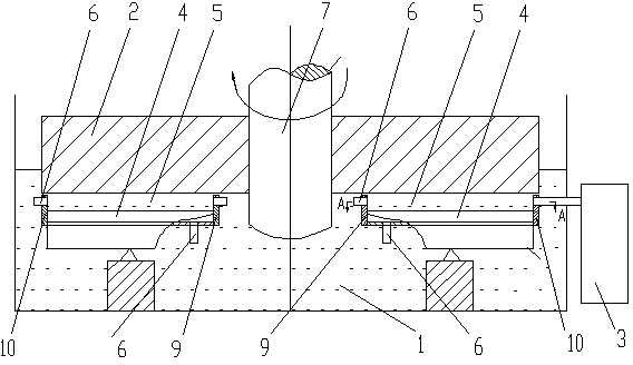
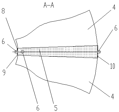
[0026] An oil supply method for a hydrodynamic thrust bearing, injecting cold oil into the oil tank 1, the oil level of the cold oil is not higher than 200mm on the working surface of the mirror plate 2; An oil inlet pipe 6 is arranged on the oil pool 5, and the oil inlet pipe 6 extends to the outside of the oil tank 1 and communicates with the external cold oil pump 3. When the hydrodynamic thrust bearing is working, the external cold oil pump 3 is turned on, and the mixed oil in the oil tank 1 is first The mirror plate 2 is driven by the rotating shaft 7 to absorb the cold oil in the oil storage tank 5 to the oil inlet end of the bearing bush 4, and the absorbed cold oil enters the bearing bush 4 and the mirror A load-bearing lubricating oil film is formed between the plates 2, and the lubricating oil in the oil film flows into the oil groove 1 to form a closed circulating oil circuit.

[0027]This embodiment is the most basic implementation mode with a simple structure. Coo...

Embodiment 2

[0029] An oil supply method for a hydrodynamic thrust bearing, injecting cold oil into the oil tank 1, the oil level of the cold oil is not higher than 200mm on the working surface of the mirror plate 2; An oil inlet pipe 6 is arranged on the oil pool 5, and the oil inlet pipe 6 extends to the outside of the oil tank 1 and communicates with the external cold oil pump 3. When the hydrodynamic thrust bearing is working, the external cold oil pump 3 is turned on, and the mixed oil in the oil tank 1 is first The mirror plate 2 is driven by the rotating shaft 7 to absorb the cold oil in the oil storage tank 5 to the oil inlet end of the bearing bush 4, and the absorbed cold oil enters the bearing bush 4 and the mirror A load-bearing lubricating oil film is formed between the plates 2, and the lubricating oil in the oil film flows into the oil groove 1 to form a closed circulating oil circuit.

[0030] The oil storage pool 5 is surrounded by two adjacent bearing pads 4 and an oil re...

Embodiment 3

[0034] An oil supply method for a hydrodynamic thrust bearing, injecting cold oil into the oil tank 1, the oil level of the cold oil is not higher than 200mm on the working surface of the mirror plate 2; An oil inlet pipe 6 is arranged on the oil pool 5, and the oil inlet pipe 6 extends to the outside of the oil tank 1 and communicates with the external cold oil pump 3. When the hydrodynamic thrust bearing is working, the external cold oil pump 3 is turned on, and the mixed oil in the oil tank 1 is first The mirror plate 2 is driven by the rotating shaft 7 to absorb the cold oil in the oil storage tank 5 to the oil inlet end of the bearing bush 4, and the absorbed cold oil enters the bearing bush 4 and the mirror A load-bearing lubricating oil film is formed between the plates 2, and the lubricating oil in the oil film flows into the oil groove 1 to form a closed circulating oil circuit.

[0035] The oil storage pool 5 is surrounded by two adjacent bearing pads 4 and an oil re...


PUM


Abstract

The invention discloses an oil supply method of a liquid dynamic pressure thrust bearing. The oil supply method comprises the following steps: injecting cold oil in an oil tank, wherein the oil level height of the cold oil is less 200mm higher than the working face of a runner plate; setting an oil inlet pipe on an oil storage pool between any two adjacent bearing bushes, wherein the oil inlet pipe is communicated with an external cold oil pump; when the liquid dynamic pressure thrust bearing works, opening the cold oil pump to pump out the mixed oil in the oil tank and then injecting the cooled oil into the oil storage pool; and adsorbing the cold oil in the oil storage pool to the oil inlet ends of the bearing bushes by a runner plate, wherein the adsorbed cold oil enters between the bearing bushes and the runner plate to form lubrication oil films and the lubrication oil in the oil films flows into the oil tank to form a closed circulating oil way. According to the oil supply method provided by the invention, oil supply is carried out through the oil storage pool, and in coordination with the low oil level in the oil tank, the stirring loss of the thrust bearing can be effectively reduced, the oil temperature rise of the whole thrust bearing can be restrained, the bearing capacity of the thrust bearing can be improved, the damage to the bearing bushes due to oil lack can be prevented and the serious accident of the main engine and economic loss can be avoided.

Description

technical field [0001] The invention relates to the technical field of sliding bearings of mechanical products, in particular to an oil supply method for a hydrodynamic thrust bearing. Background technique [0002] The hydrodynamic thrust bearing is composed of several oil wedges, and its carrying capacity is the sum of the oil film pressure of each oil wedge. It is often used in water turbines and steam turbines. The hydrodynamic thrust bearing is mainly composed of a rotating shaft, a mirror plate, a bearing bush and a bearing seat. The rotating shaft and the mirror plate are fixedly connected to drive the mirror plate to rotate. Below the surface, the bearing bush and the bearing seat are connected by equivalent support, and the bearing seat is fixed in the oil groove; the bearing bush takes the equivalent support as the fulcrum and forms a wedge-shaped gap with the mirror plate in the direction of rotation. The side is the oil outlet. When in use, the cold oil ente...

Claims


Application Information

Patent Timeline
IPC IPC(8): F16C17/12
Inventor 钟海权杨仕福廖毅刚李效振杨培平赵永智
Owner DONGFANG ELECTRIC MACHINERY
Why Eureka
Try Eureka