Catalyst drying kiln

A drying kiln and catalyst technology, which is applied in the direction of progressive dryers, drying machines, dryers, etc., can solve problems such as inability to automate production, uneven heating of products, and inability to accurately control temperature and humidity, and achieve compact and reasonable design and reduce The production cycle and the effect of reducing product deformation

Inactive Publication Date: 2014-12-10
江苏宇达环保科技股份有限公司
View PDF4 Cites 3 Cited by
  • Summary
  • Abstract
  • Description
  • Claims
  • Application Information

AI Technical Summary

Problems solved by technology

[0004] The purpose of the present invention is to provide a catalyst drying kiln to solve the problems that the existing drying k

Method used


Image

  • Catalyst drying kiln
  • Catalyst drying kiln
  • Catalyst drying kiln

Examples


Example Embodiment

[0019] The specific embodiments of the present invention will be further described below in conjunction with the drawings.

[0020] The following examples are only examples for clearly illustrating the present invention, and are not intended to limit the implementation of the present invention. For those of ordinary skill in the art, other changes or changes in different forms can be made on the basis of the following description, and these obvious changes or changes derived from the spirit of the present invention are still within the protection scope of the present invention. in.

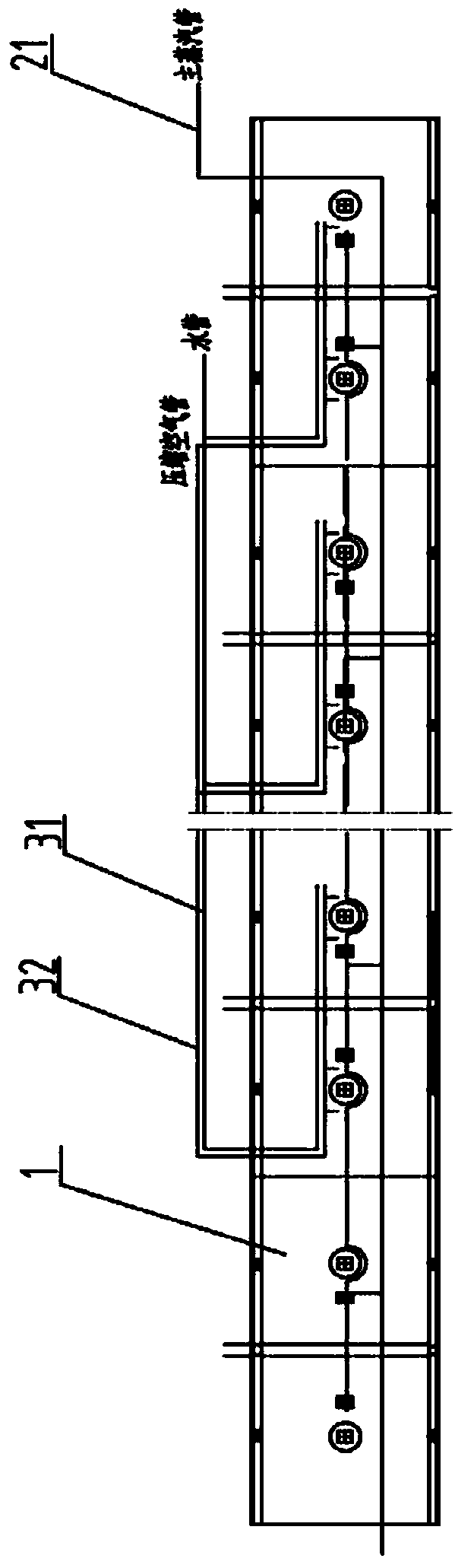
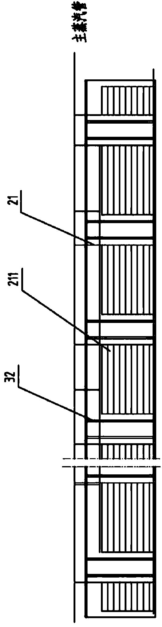
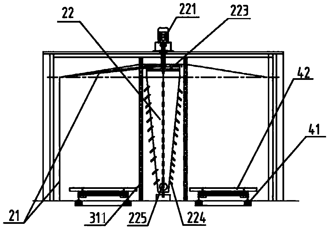
[0021] according to Figure 1-4 As shown, a catalyst drying kiln includes: a kiln body 1, a product conveying system, a gas circulation control system, a temperature control system, and a humidity control system. It is characterized in that: the kiln body 1 is a tunnel type, steel frame structure, and The kiln head and kiln end of the kiln body are equipped with automatic lifting doors, and the produ...


PUM


Abstract

The invention provides a catalyst drying kiln. The catalyst drying kiln comprises a kiln body, a temperature control system, a humidity control system and a product conveying system. The catalyst drying kiln is characterized in that the temperature control system comprises a steam pipeline and cyclones, wherein each cyclone is a hollow cavity, a motor is connected to the top of each clone, an air outlet is formed in the periphery of each cyclone, and the steam pipeline is distributed inside the kiln body. The humidity control system comprises a water pipeline and a compressed air pipeline. The catalyst drying kiln heats products evenly, substantially reduces deformation of the products and solves the problem of a low rate of finished products. A pressure sensor, a temperature sensor, a humidity sensor and an electronic valve are adopted for accurate control over the temperature and humidity. An automatic transportation by a kiln car is adopted, so that the production cost is reduced substantially, and the production cycle is shortened substantially.

Description

technical field [0001] The invention relates to a catalyst drying kiln. Background technique [0002] Catalyst drying is an important task in the catalyst production process. Now domestic manufacturers generally use box-type static drying, which uses a forklift to fork the product into the box-type room. Then, use hot air to adjust the indoor temperature, which has disadvantages such as high labor cost, easy deformation of the product, high energy consumption, low output and yield, and long production time. [0003] Cause the reason of above-mentioned problem to be: the first, production technology is backward. The product cannot be evenly heated, and the humidification cannot be precisely controlled, resulting in low yield, low output, waste of energy, and high energy consumption. Second, the use of forklifts cannot realize automated production, resulting in high labor costs. In order to solve the above problems, there is an urgent need for a new catalyst drying kiln tha...

Claims


Application Information

Patent Timeline
IPC IPC(8): F26B15/16
Inventor 唐虎戴寅戴宇
Owner 江苏宇达环保科技股份有限公司
Why Eureka
Try Eureka