Mobile terminal, shell and manufacture method thereof
A technology of mobile terminals and manufacturing methods, applied in the direction of electrical equipment shells/cabinets/drawers, electrical components, etc., can solve the problems of poor component strength and deformation, reduce production costs, reduce defective rate, and reduce the probability of deformation Effect
- Summary
- Abstract
- Description
- Claims
- Application Information
AI Technical Summary
Problems solved by technology
Method used
Image
Examples
Embodiment 1
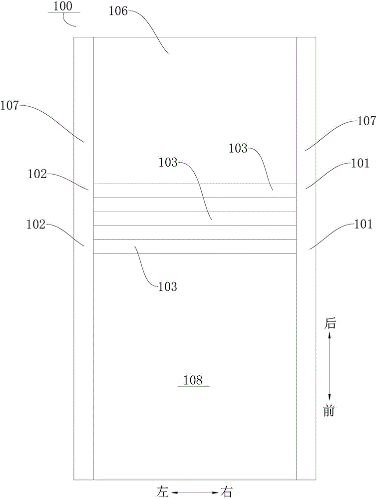
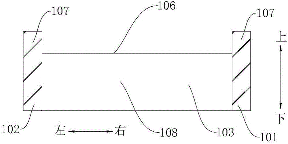
[0081] Such as Figure 1-Figure 11 As shown, the manufacturing method of the housing 110 of the mobile terminal 200 includes the following steps:
[0082] S11 : providing a base material 100 , and processing an installation groove 106 on the base material 100 . Such as figure 1 , figure 2 As shown, the mounting groove 106 is formed on the upper surface of the substrate 100, and the opening of the mounting groove 106 is upward. It should be noted that the substrate 100 may be a substrate 100 having a conductive function, such as a metal substrate 100 . Of course, the base material 100 can also be a plastic base material 100. In order to make the housing 110 formed by the plastic base material 100 satisfy the use function of the mobile terminal 200, it is necessary to make the housing 110 have a conductive function. 100 is laid with conductive plating.
[0083] S12: Machining a plurality of spaced apart slits 103, the number of slits 103 can be 2, 3, 4 or 5, the slits 103 ...
Embodiment 2
[0090] Such as Figure 1-Figure 8 and Figure 12 As shown, different from Embodiment 1, in this embodiment, step S50 includes the following sub-steps:
[0091] S51: Take off the fixing part 120 .
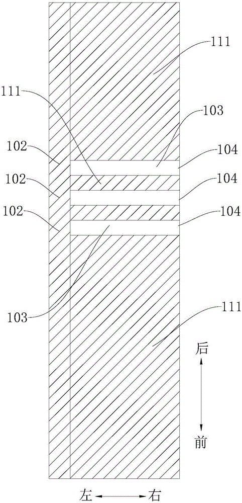
[0092] S52 : Cutting the two ends of the gap 103 respectively to form the casing 110 , wherein the gap 103 on the casing 110 is completely filled with the filler 105 . Such as Figure 7 As shown, the remaining material 109 located at the left edge of the base material 100 is cut along the front-rear direction, and the remaining material 109 located at the right edge of the base material 100 is cut along the front-rear direction, thereby obtaining a housing 110 located at The slit 103 on the housing 110 extends along the left and right direction, and the slit 103 divides the housing 110 into a plurality of regions 111, and the plurality of regions 111 are distributed at intervals along the vertical direction, and the slit 103 on the housing 110 is completely filled with fillers 10...
Embodiment 3
[0094] Such as Figure 1-Figure 8 and Figure 13 As shown, different from Embodiment 1, in this embodiment, step S50 includes the following sub-steps:
[0095] S'51: Take off the fixing piece 120.
[0096] S'52: Fill the portion of the gap 103 occupied by the fixing piece 120 with the filler 105. S'53: cutting the second closed section 102 to form the casing 110, the casing 110 is divided into a plurality of spaced areas 111 by the gap 103, wherein the gap 103 on the casing 110 is completely filled by the filler 105.
[0097] It can be understood that the part of the gap 103 not occupied by the fixing part 120 can be filled for the first time, and then the fixing part 120 can be removed, and then the part of the gap 103 occupied by the fixing part 120 can be filled for the second time. When filling for the first time, the fixing member 120 can play a supporting role, so as to prevent the gap 103 from being deformed due to excessive filling pressure. During the second filli...
PUM
 Abstract
Description
Claims
Application Information
 - R&D
- Intellectual Property
- Life Sciences
- Materials
- Tech Scout
- Unparalleled Data Quality
- Higher Quality Content
- 60% Fewer Hallucinations
Browse by: Latest US Patents, China's latest patents, Technical Efficacy Thesaurus, Application Domain, Technology Topic, Popular Technical Reports.
© 2025 PatSnap. All rights reserved.Legal|Privacy policy|Modern Slavery Act Transparency Statement|Sitemap|About US| Contact US: help@patsnap.com


