
A photoelectric correction sensor for variable translucent coils and its detection method
A technology of photoelectric deviation correction and photoelectric detection, applied in the direction of using optical devices, instruments, measuring devices, etc., can solve the problems of poor deviation correction effect of the tested strips
- Summary
- Abstract
- Description
- Claims
- Application Information
AI Technical Summary
Problems solved by technology
Method used
Image

Examples
example 1
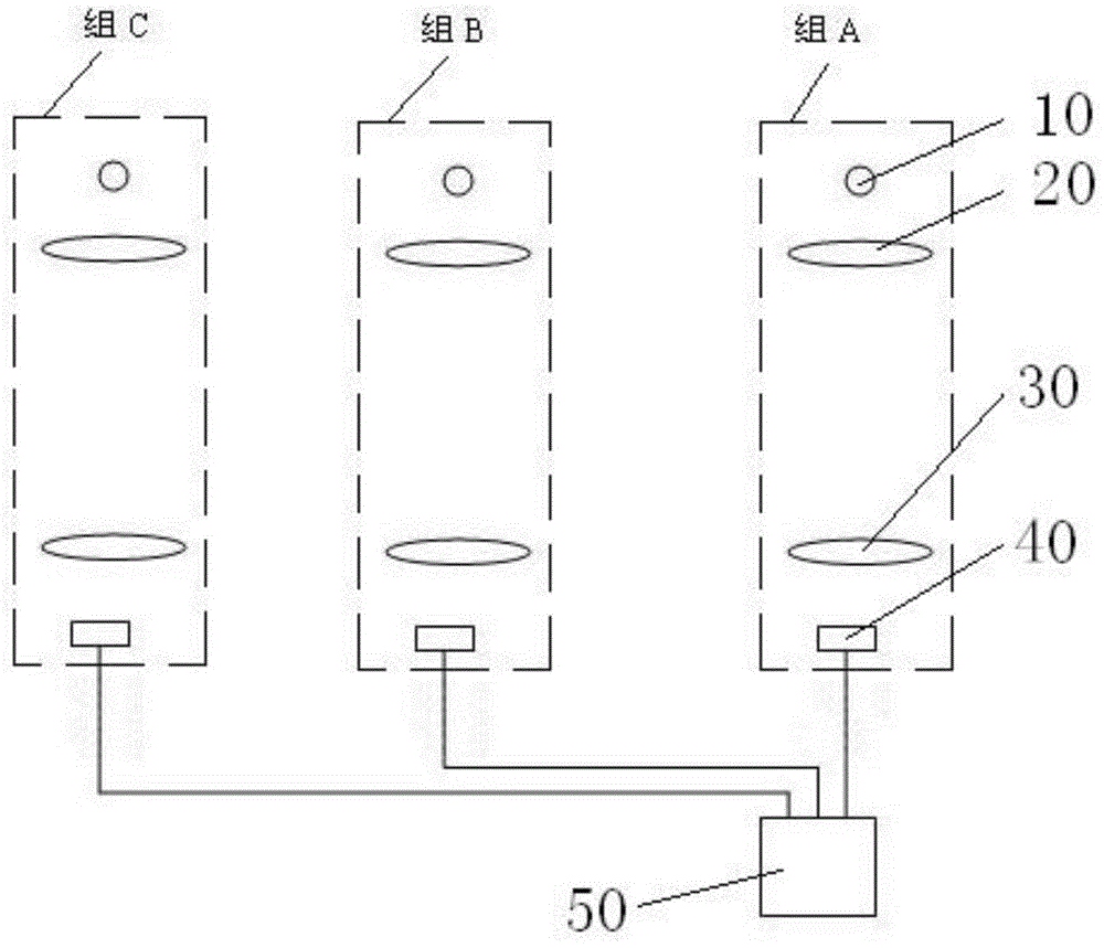
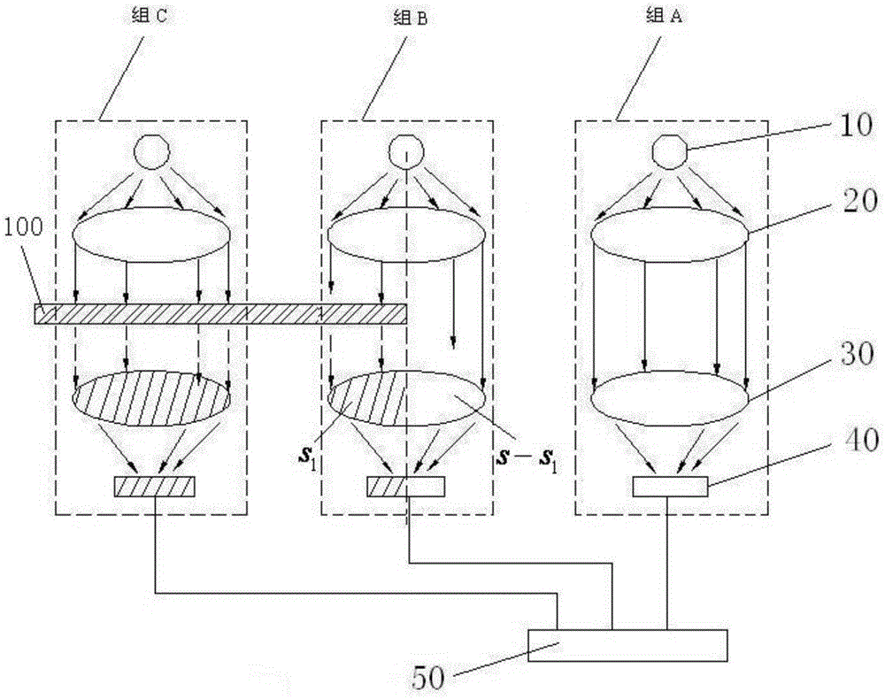
[0051] Example 1: A photoelectric correction sensor for variable translucent coils, see figure 1 , figure 2 As shown, it includes two brackets (the brackets are not shown in the description of the drawings), one of which is fixedly connected to the coiler near the front end of the longitudinal running section of the strip to be tested, and the other bracket is fixedly connected to the coiler near the front end of the strip to be tested. On the coiler above the rear end side of the longitudinal walking section of the material. And three groups of identical photoelectric detection units are arranged horizontally side by side on each bracket, and these three groups of identical photoelectric detection units are respectively marked as group A, group B and group C. Each group of photoelectric detection units includes a light source 10, a No. 1 collimator lens 20 that can generate parallel light, a No. 2 collimator lens 30 that can condense light, and a photosensitive device 40, a...
example 2
[0078] Example 2: A detection method of a photoelectric correction sensor for variable translucent coils, see figure 1 , figure 2 As shown, if in step 2 of Example 1, when laying out the strip to be tested on the coiler, the strip to be tested is arranged horizontally so that the center of the No. 1 collimator lens and the center of No. 2 collimator lens The center line of the test strip is perpendicular to the horizontal plane of the tested strip, and the edge of one side of the tested strip and the center line fall together in a longitudinal vertical plane, so that the second collimator lens of group B is tested The area s of the strip shade 1 is half of the light transmission area s of the No. 2 collimator lens of group B, namely
[0079] The detection method and working process of the photoelectric detection unit in the second example are the same as the first example, because the area s of the No. 2 collimator lens of group B is blocked by the strip to be tested 1 i...
example 3
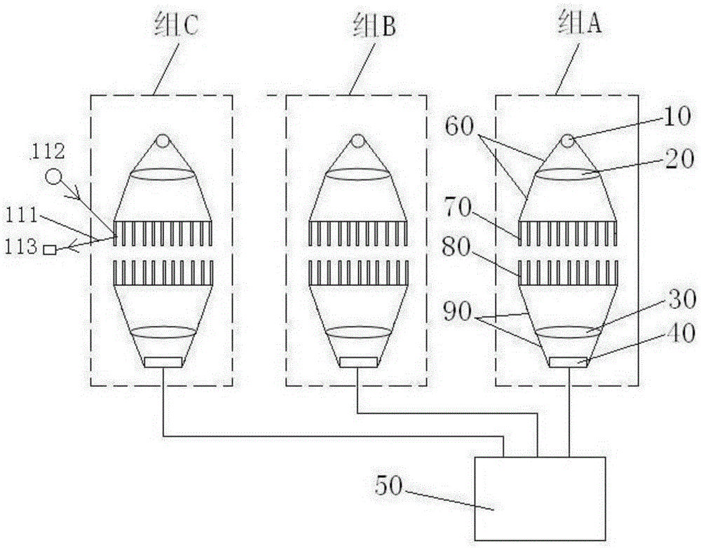
[0080] Example 3: A photoelectric correction sensor for variable translucent coils, see image 3 As shown, Example 3 is a schematic diagram of the structure and principle after adding the upper light-absorbing cover, the lower light-absorbing cover, the upper flexible light-absorbing curtain whiskers and the lower flexible light-absorbing curtain to the structural principle schematic diagram of Example 1. An upper light-absorbing sleeve 60 is tightly connected to the edge of the No. 1 collimator lens, and the upper end of the upper light-absorbing sleeve is tightly connected to the lamp holder of the light source. The opening diameter of the lower end of the upper light-absorbing sleeve is larger than the diameter of the No. 1 collimator lens. A plurality of upper flexible light-absorbing curtain whiskers 70 freely facing downwards are connected to the edge of the lower opening of the upper light-absorbing sleeve, and the length of each upper flexible light-absorbing curtain wh...
PUM
 Abstract
Description
Claims
Application Information