Carrier for object to be detected

A technology for the object to be tested and the carrier, which is applied in the field of the object to be tested, can solve the problems of destroying the linearity and flatness of the product, deformation of the surface cover, and great influence, so as to reduce the contact area, increase the service life, and reduce the pollution effect

Pending Publication Date: 2022-08-02
厦门威芯泰科技有限公司
View PDF0 Cites 0 Cited by
  • Summary
  • Abstract
  • Description
  • Claims
  • Application Information

AI Technical Summary

Problems solved by technology

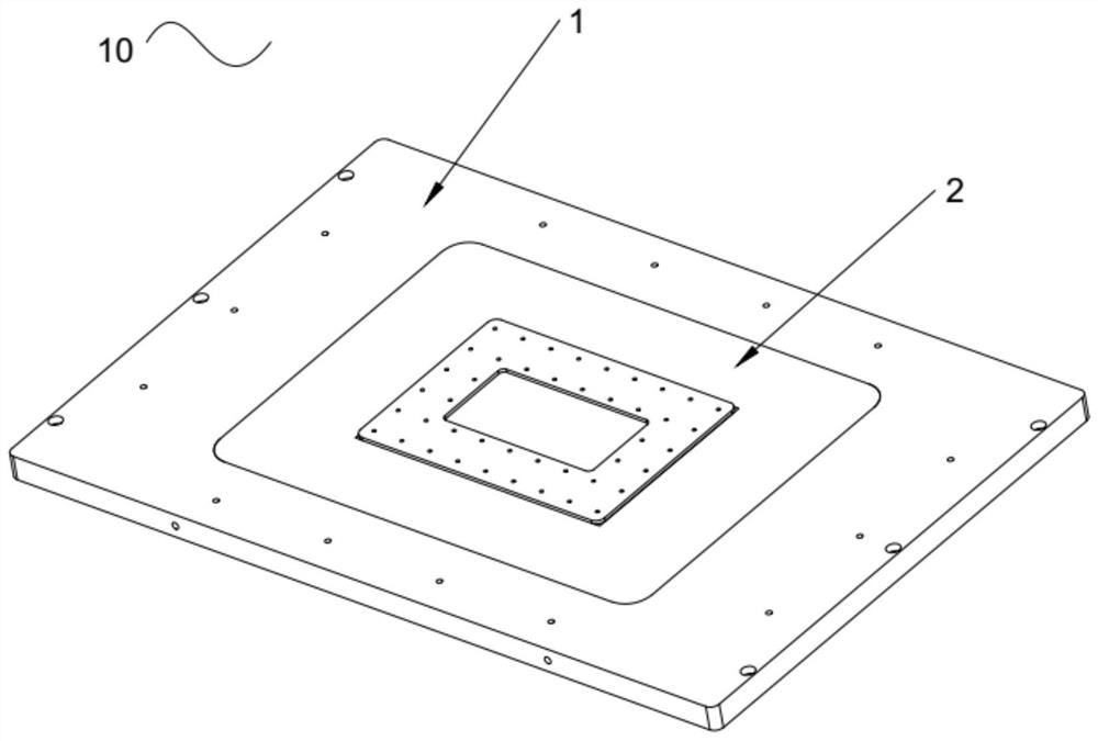
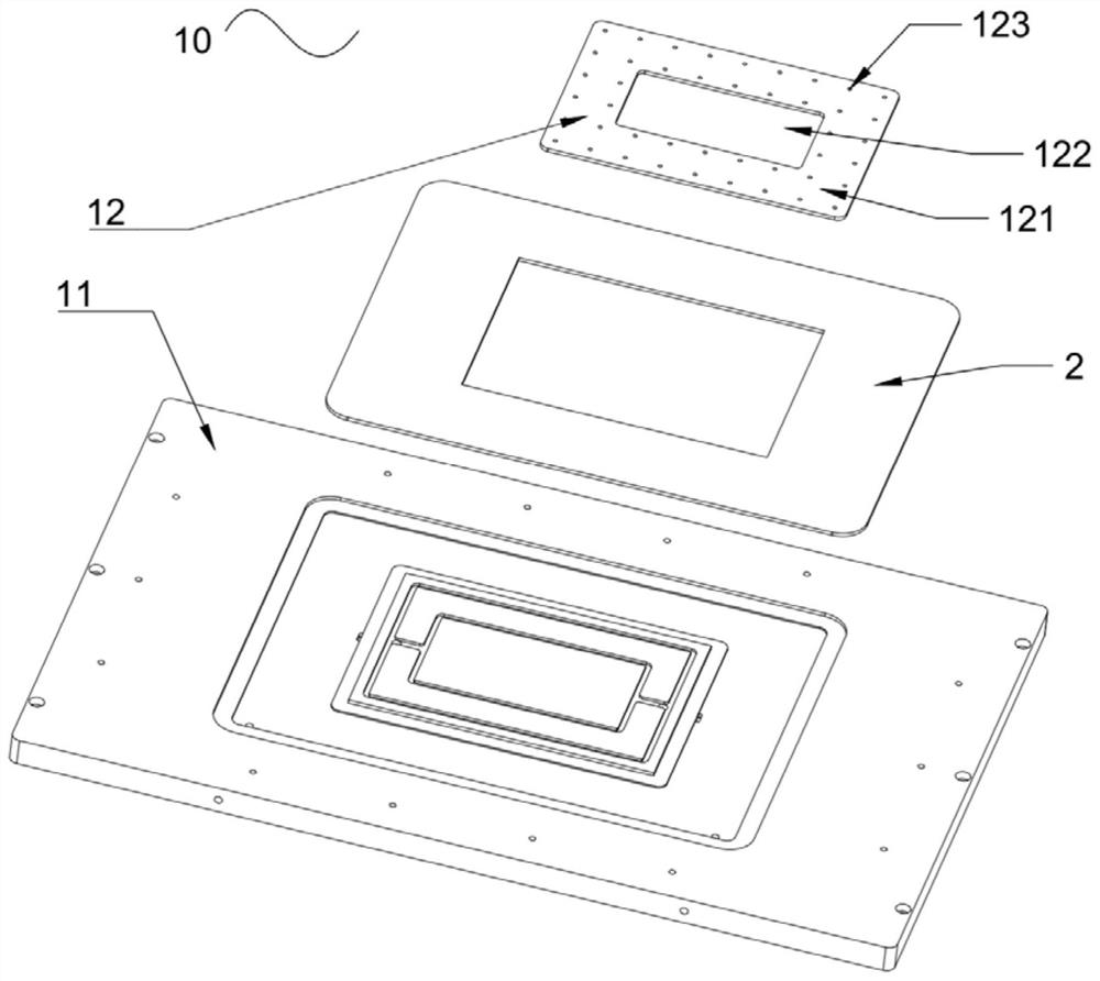
[0004] The purpose of the present invention is to overcome the surface cover existing in the background technology when it is made of transparent acrylic plate, because the thickness of the surface cover itself is not large when it is prepared to save material, and there are adsorption holes on it, so when it is used Both the vacuum tank and the adsorption hole are subject to atmospheric pressure, and the adsorption hole has a greater impact on it, which easily causes the cover to deform downward. When the cover is placed on it, the cover is also deformed accordingly, destroying the straight line of the product To solve the problems of stability and flatness, provide a carrier for the object to be tested

Method used


Image

  • Carrier for object to be detected
  • Carrier for object to be detected
  • Carrier for object to be detected

Examples


Embodiment Construction

[0046] The technical solutions in the embodiments of the present invention will be clearly and completely described below with reference to the accompanying drawings in the embodiments of the present invention. Obviously, the described embodiments are preferred embodiments of the present invention and should not be construed to exclude other embodiments. Based on the embodiments of the present invention, all other embodiments obtained by those of ordinary skill in the art without creative efforts fall within the protection scope of the present invention.

[0047] In the claims, description and the above drawings of the present invention, unless otherwise clearly defined, the terms "first", "second" or "third" are used to distinguish different objects, rather than used for Describe a specific order.

[0048] In the claims, description and the above drawings of the present invention, unless otherwise expressly defined, the terms "center", "horizontal", "longitudinal", "horizont...


PUM


Abstract

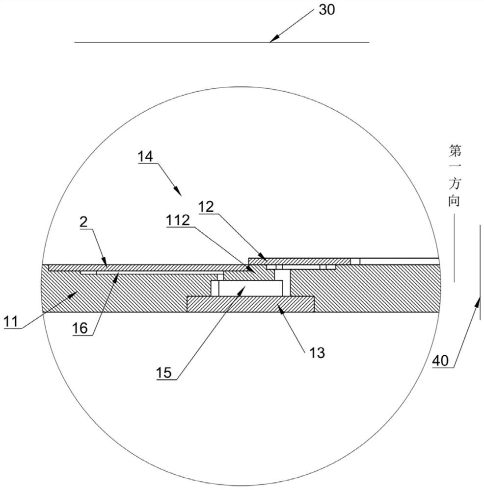
The invention discloses a to-be-tested object carrier which comprises a base and a surface cover, the base is provided with a bump and a vacuum groove surrounding the bump along a first direction, the base is also provided with a first channel and a second channel, the bump is provided with a bearing surface for bearing a to-be-tested object, the first channel is used for communicating the vacuum groove with an external vacuum source, and the second channel is used for communicating the vacuum groove with an external vacuum source. The second channel is communicated with the vacuum tank and opened on the bearing surface; the projection of the bump and the projection of the second channel on the first plane are suitable for being located in a non-detection area; the vacuum tank is configured in a way that the first detection area is suitable for being located in a projection on a first plane; the projection of the first channel on the first plane is located outside the projection of the object to be measured on the first plane; the surface cover hermetically covers the vacuum tank, and the surface cover and the vacuum tank define a vacuum cavity; and the projection of the vacuum tank and the surface cover on the first plane and the overlapped part of the first detection area are configured to be suitable for light transmission. The surface cover is prevented from deforming and the to-be-detected object is prevented from being damaged.

Description

technical field [0001] The invention relates to the field of cover plate detection, in particular to a test object carrier. Background technique [0002] In the inspection field of transparent cover plates, such as mobile phone cover plates, it is necessary to transmit the light source and then use the camera to obtain images. According to the obtained images, it is judged whether the cover plate in the inspection area is defective; the carrier is used to support the transparent cover plate and For light source transmission, the carrier is provided with a vertical upward adsorption hole to absorb the middle of the cover plate and prevent the cover plate from running; since the bottom of the carrier is provided with a surface light source and a moving part, the light transmits the carrier from the bottom Therefore, if the vacuum source is installed at the bottom of the carrier and is connected to the adsorption hole, the pipeline of the vacuum source needs to pass through the...

Claims


Application Information

Patent Timeline
Patent Type & Authority Applications(China)
IPC IPC(8): G01N21/88G01N21/01
CPCG01N21/88G01N21/01G01N2021/0112
Inventor 文公立卓文强马梓万朱朝军张建城王磊
Owner 厦门威芯泰科技有限公司
Why Eureka
Try Eureka