Adhering device for fishing rod decorative strip

A mounting device and decorative strip technology, which is applied in the field of mounting devices for fishing rod decorative strips, can solve problems such as inaccurate placement, easy generation of dust, and partial sticking of decorative strips, and achieve fast processing speed, good processing quality, well-designed effects

Inactive Publication Date: 2015-01-28
蔡留保
View PDF4 Cites 4 Cited by
  • Summary
  • Abstract
  • Description
  • Claims
  • Application Information

AI Technical Summary

Problems solved by technology

[0002] After the fishing rod is produced, for the sake of aesthetics or trademark brand, a decorative strip or a CP strip with a trademark brand needs to be pasted on the fishing rod. The current mounting method is that the worker puts the fishing rod on the table and aligns the For the decorative strips that need to be mounted, manually roll the fishing rod on the table for mounting, and this mounting method is likely to cause the decorative strip to be biased, although some equipment can place the fishing rod on the roller frame , through the rotation of the roller and then mount, but there is still the phenomenon of inaccurate placement, it needs to be torn off and re-attached, which not only wastes time, but also affects the appearance of the fishing rod, and some materials will be damaged during the tear-off process , you need to re-select raw materials, which will affect the economic benefits of the enterprise, and it is easy to generate dust when the fish tank is placed. The decorative strips of the fishing rods covered with dust are easy to fall off after the mounting device strips, which affects the quality of the product.

Method used


Image

  • Adhering device for fishing rod decorative strip

Examples


Embodiment Construction

[0014] In order to deepen the understanding of the present invention, the present invention will be described in further detail below in conjunction with the accompanying drawings and embodiments, which are only used to explain the present invention and do not limit the protection scope of the present invention.

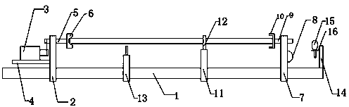
[0015] Such as figure 1 As shown, the present invention is a mounting device for fishing rod decorative strips. The mounting device includes a linear guide rail 1 arranged on a base, and a fixed base 2 is provided on one side of the linear guide rail 1. One side of the base 2 is provided with a support plate 4 supporting the micromotor 3, and the fixed base 2 is provided with a rotating shaft 5 driven by the motor, and the rotating shaft 5 rotates under the drive of the motor. One side of 5 is provided with a rotating support seat 6, and the inner diameter of the rotating support seat 6 becomes smaller from the opening to the inside, so that the fishing rod ...


PUM


Abstract

The invention discloses an adhering device for a fishing rod decorative strip. The adhering device comprises a linear guide rail arranged on a base, wherein a fixed base is arranged on one side of the linear guide rail, a supporting plate used for supporting a micro-motor is arranged on one side of the fixed base, a rotary shaft which is driven to rotate by the micro-motor is arranged on the fixed base, a rotary supporting base is arranged on one side of the rotary shaft, a movable base is further arranged on the other side of the linear guide rail, a driven shaft is arranged on the movable base, a driven supporting base is arranged on one side of the driven shaft, a horizontal base and a decorative strip base are further arranged on the linear guide rail, a U-shaped supporting block is arranged on the horizontal base, and a decorative strip to be adhered is arranged on the decorative strip base. The adhering device has a simple structure, and is reasonable in design, convenient to operate, capable of rapidly adhering a decorative strip to a fishing rod, high in processing speed and good in processing quality.

Description

technical field [0001] The invention belongs to the technical field of production and processing of fishing rods, and in particular relates to a mounting device for fishing rod decorative strips. Background technique [0002] After the fishing rod is produced, for the sake of aesthetics or trademark brand, a decorative strip or a CP strip with a trademark brand needs to be pasted on the fishing rod. The current mounting method is that the worker puts the fishing rod on the table and aligns the For the decorative strips that need to be mounted, manually roll the fishing rod on the table for mounting, and this mounting method is likely to cause the decorative strip to be biased, although some equipment can place the fishing rod on the roller frame , through the rotation of the roller and then mount, but there is still the phenomenon of inaccurate placement, it needs to be torn off and re-attached, which not only wastes time, but also affects the appearance of the fishi...

Claims


Application Information

Patent Timeline
Patent Type & Authority Applications(China)
IPC IPC(8): B65C3/02
CPCB65C3/02B65C9/04B65C9/26
Inventor 蔡留保
Owner 蔡留保
Why Eureka
Try Eureka