Simulation setup for aerodynamically synchronized separation of combined segment models

A technology of synchronous separation and simulation device, which is applied in the direction of aerodynamic test, measuring device, machine/structural component test, etc., and can solve the problems of low adjustment accuracy of aerodynamic force and wind angle of attack, etc.

Active Publication Date: 2017-07-25
CENT SOUTH UNIV +1
View PDF5 Cites 0 Cited by
  • Summary
  • Abstract
  • Description
  • Claims
  • Application Information

AI Technical Summary

Problems solved by technology

In order to solve the problem that the existing rigid force-measuring segmental model device cannot simultaneously test the aerodynamic force of each model in the combined segmental model system, and the adjustment accuracy of the wind angle of attack is not high

Method used


Image

  • Simulation setup for aerodynamically synchronized separation of combined segment models
  • Simulation setup for aerodynamically synchronized separation of combined segment models
  • Simulation setup for aerodynamically synchronized separation of combined segment models

Examples


Embodiment 1

[0046] Embodiment 1 provides an aerodynamic synchronous separation method for a combined segmental model system that is convenient for adjusting the wind angle of attack:

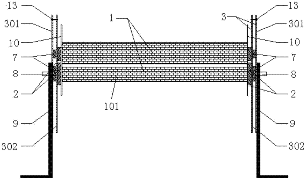
[0047] (1) Install two load-measuring balances 2 at both ends of each combined segment model 101 of the combined model 1, and the distance between the combined segment models 101 can be moved along the axial direction of the slide bar 6 by the combined segment model 101 and / or Or the sliding rod 6 moves vertically along the chute to ensure that the distance between the combined segment models 101 is geometrically similar to the actual distance. There is an end plate 10 between the force-measuring balance 2 and the combined model to reduce the disturbance of the accessory components to the flow field around the model.

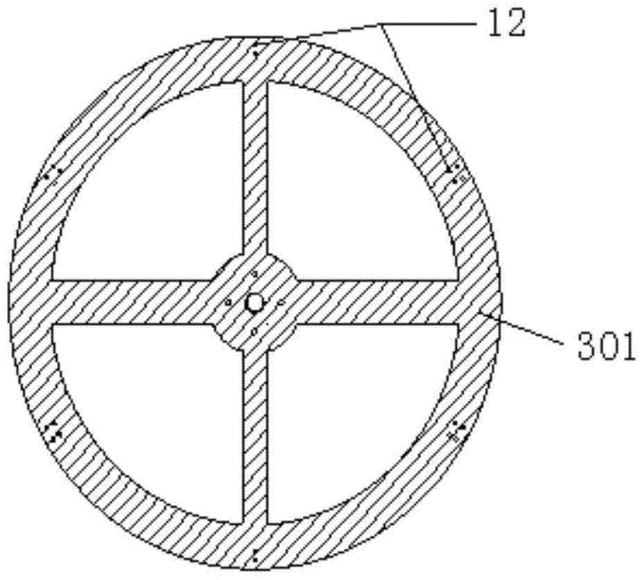
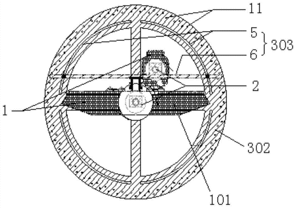
[0048] (2) force-measuring balance 2 and combined model 1 are fixed on the disc-shaped angle regulator rotating disk 302 by balance fixed block 7; force-measuring balance 2, combined model 1 ...

Embodiment 2

[0052] Embodiment 2 A combined segmental model system aerodynamic synchronous separation method that is convenient for adjusting the wind angle of attack, such as figure 1 As shown, taking the train-bridge system as an example, the train is usually composed of multiple carriages, and the length is relatively large. It can be considered that it is the same as a long-span bridge, and it approximately conforms to the strip assumption. Its aerodynamic force can be measured through the combined segment model. hole test. Due to the small windward area of ​​the wheels, the impact on the aerodynamic force of the train is small, the simulation of the wheels can be ignored during the test, and the distance between the train and the bridge is kept at the height of the wheels. Install two force-measuring balances 2 at both ends of each combined segment model 101 in the train-bridge combination model 1, and there is an end plate 10 between the force-measuring balance 2 and the combined mod...


PUM


Abstract

The invention discloses a simulator used for sync separation of aerodynamic force of combined segment models. The simulator comprises a combined model being composed of at least two combined segment models. The two ends of each combined segment model are each provided with a force measurement balance used for testing aerodynamic force of the corresponding combined segment model. The ends of the combined segment models are fixedly connected with combination regulation mechanisms used for regulating space between two adjacent combined segment models and wind attack angles of the combined segment models; and / or the combined segment models are fixedly connected to combination regulation mechanisms used for regulating space between two adjacent combined segment models and wind attack angles of the combined segment models through the force measurement balances at the ends. The two ends of each combined segment model are each provided with one set of combination regulation mechanisms. According to the simulator, the aerodynamic force of the combined segment models in the combined model at different wind attack angle states can be tested synchronously.

Description

technical field [0001] The invention relates to the technical field of aerodynamic synchronous separation of combined segment model systems, in particular to a simulation device for aerodynamic synchronous separation of combined segment models. Background technique [0002] The structure is always affected by the aerodynamic interference of adjacent structures, and the actual wind load it receives is often different from the wind load provisions in the relevant codes that are only applicable to individual structures. This kind of aerodynamic interference is very complicated, and usually cannot be obtained through theoretical analysis. It is necessary to carry out special wind load research, and the segmental model wind tunnel test is one of the effective means commonly used for such research. The so-called segmental model, which only examines a part of the structure and applies the wind load on this part of the structure to the overall structure, is suitable for studying str...

Claims


Application Information

Patent Timeline
Patent Type & Authority Patents(China)
IPC IPC(8): G01M9/08
Inventor 邹云峰何旭辉李欢贺俊周佳
Owner CENT SOUTH UNIV
Why Eureka
Try Eureka