A fuel injection control valve and a high-pressure common rail fuel injection system using the fuel injection control valve

A technology of control valves and electromagnetic control valves, which is applied in the direction of fuel injection devices, charging systems, engine components, etc., can solve the difficulty of processing key parts of electronically controlled fuel injectors, restrict the promotion and application of common rail systems, and product qualification Low efficiency and other problems, to achieve the effect of improving fuel injection response speed, increasing service life and improving combustion characteristics

Active Publication Date: 2016-09-07
NANYUE FUEL INJECTION SYST CO LTD
View PDF5 Cites 0 Cited by
  • Summary
  • Abstract
  • Description
  • Claims
  • Application Information

AI Technical Summary

Problems solved by technology

Due to the difficulty in processing the key components of the electronically controlled fuel injector, the product qualification rate is low; the requirements for oil products, product cleanliness and operating environment are extremely strict, and the maintenance cost is high
These high requirements restrict the popularization and application of the common rail system to a certain extent.

Method used


Image

  • A fuel injection control valve and a high-pressure common rail fuel injection system using the fuel injection control valve
  • A fuel injection control valve and a high-pressure common rail fuel injection system using the fuel injection control valve
  • A fuel injection control valve and a high-pressure common rail fuel injection system using the fuel injection control valve

Examples


Embodiment Construction

[0045] In order to make the technical means, creative features, goals and effects achieved by the present invention easy to understand, the present invention will be further described below in conjunction with specific illustrations.

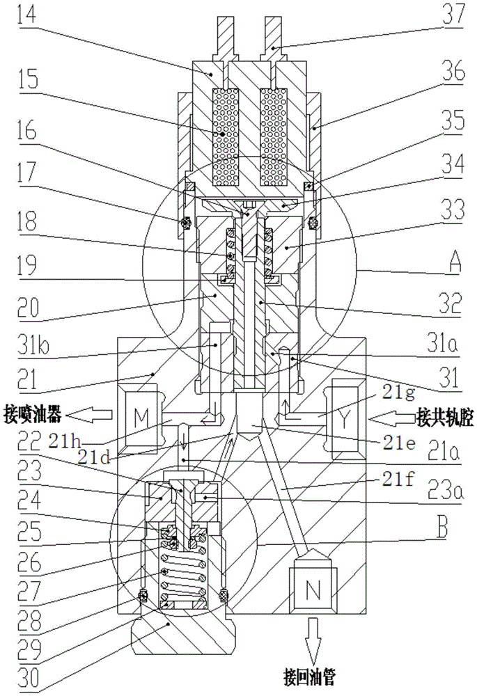
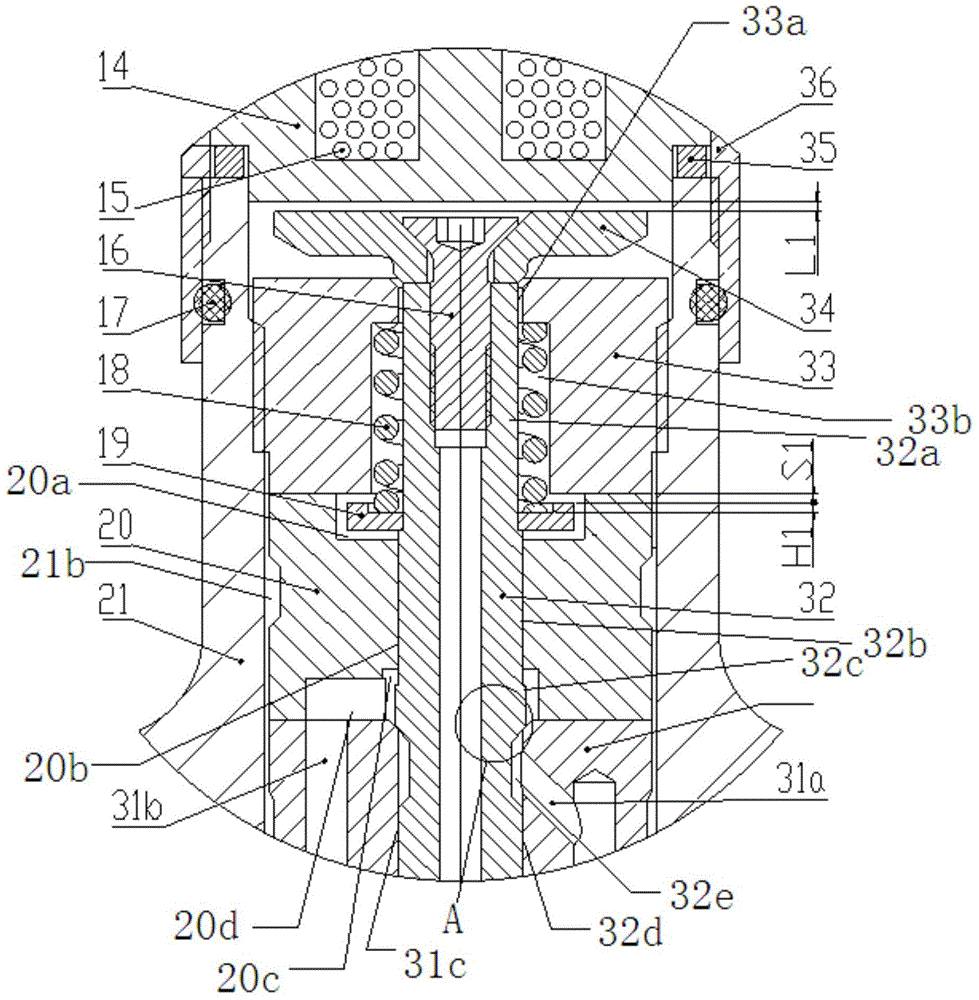
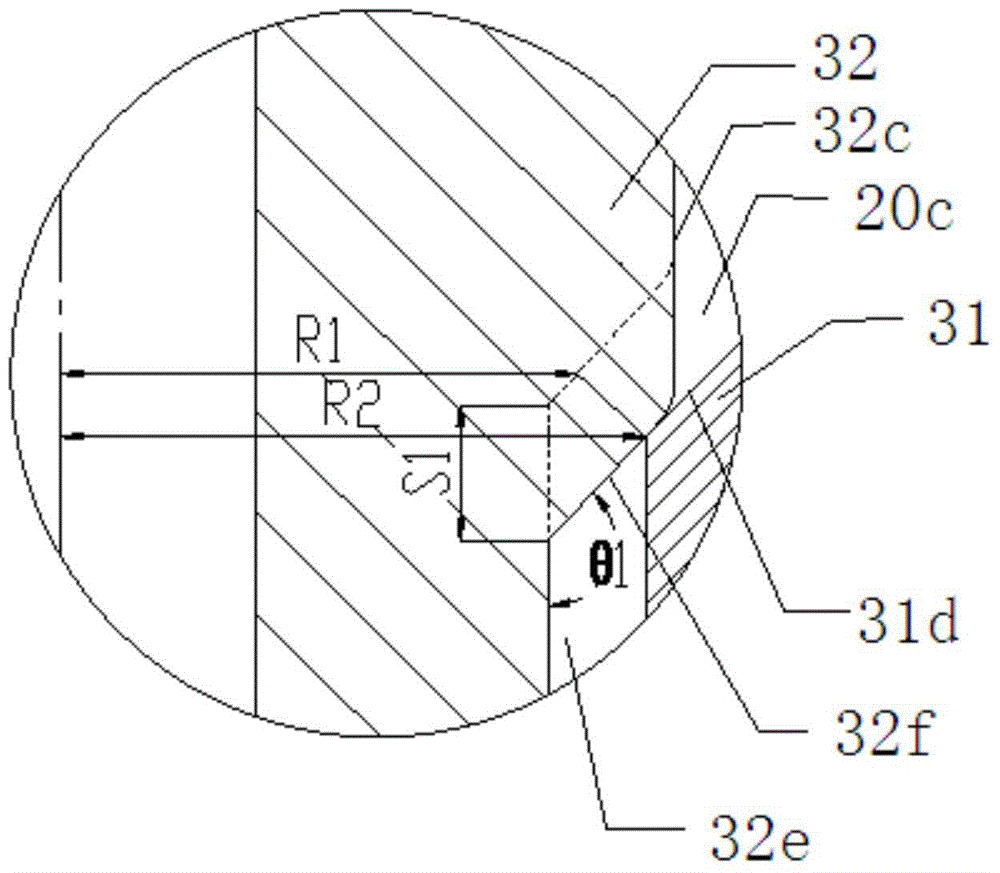
[0046] see Figure 1 to Figure 5 , the fuel injection control valve shown in the figure includes a valve body 21, an electromagnetic control valve component and a pressure relief valve component.

[0047] The upper part of the valve body 21 is provided with an electromagnetic control valve component installation cavity 21b, the two sides of the middle part are respectively provided with a common rail cavity interface Y and an injector interface M, and the lower part is equipped with a pressure relief valve component installation cavity 21c and an oil return pipe interface N; The valve body 21 is equipped with a pressure relief valve oil inlet passage 21d, an oil relief valve return oil passage 21a, an oil return chamber 21e, a total oil return p...


PUM


Abstract

The invention discloses a fuel injection control valve and a high-pressure common rail fuel injection system comprising the fuel injection control valve. The fuel injection control valve is composed of a valve body, a solenoid electric valve component and a decompression valve component. The fuel injection beginning point is changed by adjusting the power-on beginning point of an excitation coil, and the fuel injection quantity is changed by adjusting the power-on time of the excitation coil. The flow area of the solenoid electric valve component is larger than the flow area of the decompression valve component, and the opening pressure of the decompression valve component is slightly higher than the opening pressure of a fuel injector so as to obtain the fuel injection characteristics of slow first and urgent second and increase the fuel injection response speed. The decompression valve component enables the fuel injector to be in a fuel drainage state at the final stage of fuel injection, so the fuel injector can cut off fuel more rapidly. A control valve element of the decompression valve component is of a fuel pressure self-balancing form structure, so the driving current of the excitation coil can be reduced, and the service life of a solenoid valve can be prolonged. According to the high-pressure common rail fuel injection system, since the fuel injection control valve and the mechanical fuel injector are combined, flexible control over the fuel injection beginning point and the fuel injection quantity can be achieved.

Description

technical field [0001] The invention relates to a fuel injection control valve capable of controlling fuel injection starting point and fuel injection quantity, and a high-pressure common rail fuel injection system using the fuel injection control valve. Background technique [0002] In the fuel supply system of diesel engine, the traditional mechanical fuel injection system has little control freedom and low control precision, so it is difficult to ensure that each fuel injection parameter is optimally controlled according to the corresponding engine operating conditions. The common rail system has changed the composition of the traditional mechanical fuel injection pump system. The generation of its fuel injection pressure is completely independent of the engine speed and injection process. The independent and flexible control of secondary injection greatly improves the comprehensive performance of the diesel engine in terms of power, economy, emission and noise. Common r...

Claims


Application Information

Patent Timeline
Patent Type & Authority Patents(China)
IPC IPC(8): F02M51/06F02M61/16
Inventor 龙美彪欧阳玲湘黄民备刘成谭四喜
Owner NANYUE FUEL INJECTION SYST CO LTD
Why Eureka
Try Eureka