Digital automatic control oil pumping method and mobile balancing digital oil pumping unit

A pumping unit and balancing technology, which is applied to the automatic control system of drilling, pump control, machine/engine, etc., can solve the problems of low balance rate, high production cost, and inability to automatically adjust the stroke, so as to improve the balance rate, Easy to use and reasonable structure

Active Publication Date: 2015-04-29
XINJIANG UYGUR AUTONOMOUS REGION NO 3 MACHINE TOOL WORKS
View PDF6 Cites 21 Cited by
  • Summary
  • Abstract
  • Description
  • Claims
  • Application Information

AI Technical Summary

Problems solved by technology

[0003] The present invention provides a digitalized automatic control oil pumping method and a moving balance digitalized pumping unit, which overcomes the above-mentioned deficiencies in the prior art, and can effectively solve the problem that the existing beam pumping unit cannot automatically adjust the balance and c

Method used


Image

  • Digital automatic control oil pumping method and mobile balancing digital oil pumping unit
  • Digital automatic control oil pumping method and mobile balancing digital oil pumping unit
  • Digital automatic control oil pumping method and mobile balancing digital oil pumping unit

Examples


Embodiment 1

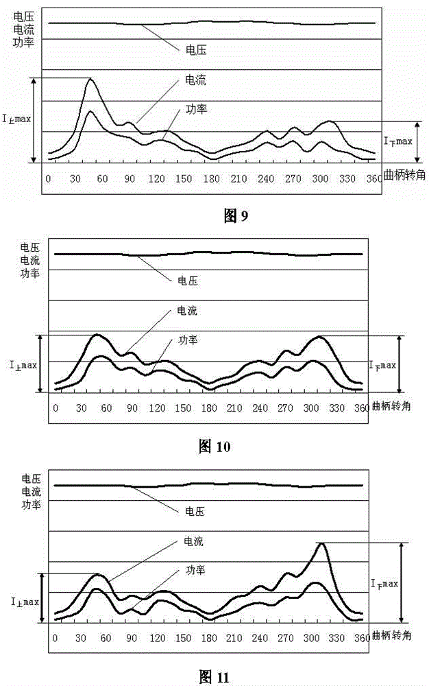
[0043] Embodiment 1, as attached Figure 9 , 10 , shown in 11, the digitalized automatic control oil pumping method includes a mobile balance digitalized pumping unit, and the mobile balanced digitalized pumping unit includes a main motor 15, a beam 3, a balance boom 7, a crank 9 and a rope hanger 1, A balance boom 7 is fixedly installed on the left end of the beam 3, and a mobile counterweight box 28 and a driving device capable of moving the mobile counterweight box 28 to the left and right are respectively installed on the balance boom 7. There is a stroke process measuring device, and a load sensor 17 is fixedly installed on the rope suspension device 1; a central processing unit and a three-phase electrical parameter acquisition device are also included, and the three-phase electrical parameter acquisition device is installed on the power supply input end; the method presses The above steps are carried out:

[0044] The first step is to transmit the data collected ...

Embodiment 2

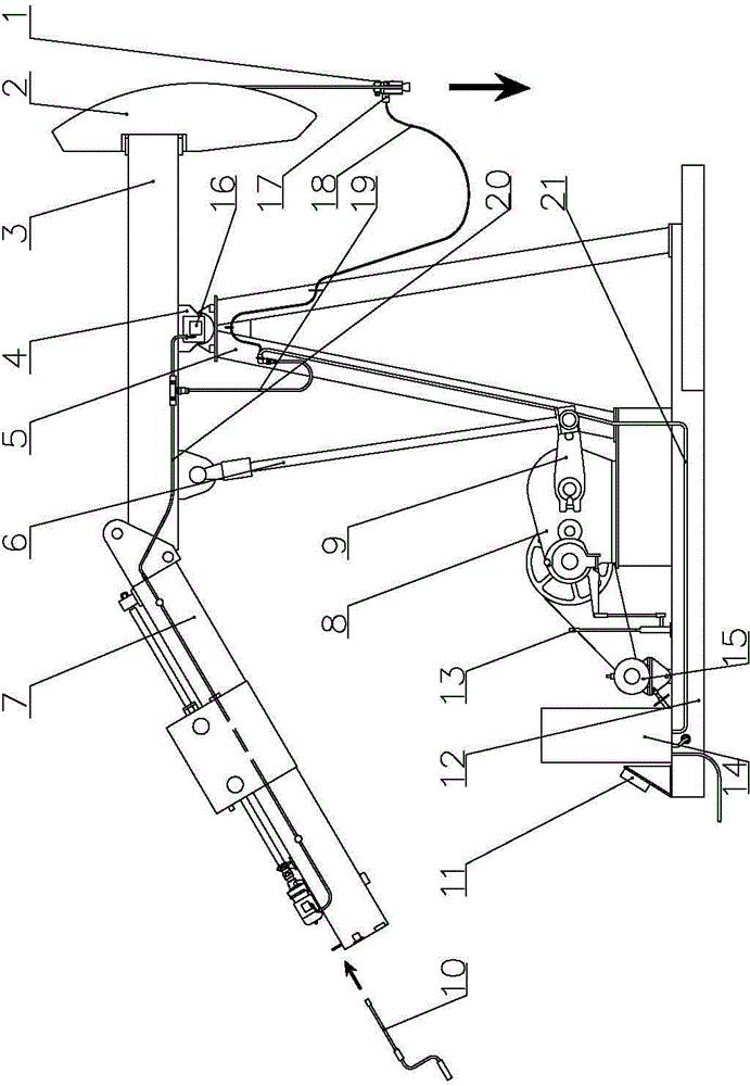
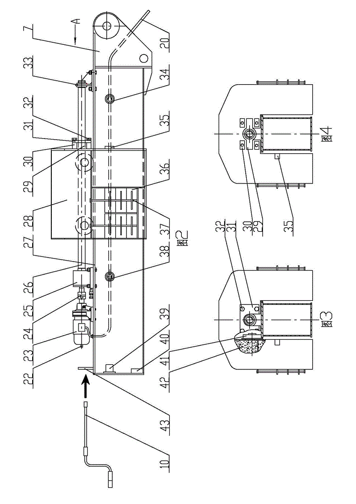
[0065] Embodiment 2, as attached figure 1 , 2 , 3, and 4, the mobile balance digital pumping unit includes a main motor 15, a reducer 8, a crank 9, a connecting rod 6, a beam 3, a balance boom 7, a support 5, a donkey head 2, a base 12, a brake Device 13, rope suspension device 1 and stroke process measuring device; main motor 15, reducer 8, brake device 13 and bracket 5 are fixedly installed on base 12, and the beam 3 that can swing up and down passes through the beam support 4 in the middle Hinged on the top of the bracket 5, a crank 9 is installed on the power output shaft of the reducer 8, the lower end of the connecting rod 6 is hinged with the crank 9, the upper end of the connecting rod 6 is hinged on the left part of the beam 3, and the beam 3 The donkey head 2 is fixedly installed on the right end of the donkey head 2, the rope suspension device 1 is installed on the donkey head 2, the balance boom 7 is fixedly installed on the left end of the beam 3, and the mob...


PUM


Abstract

The invention relates to the technical field of beam-pumping units and discloses a digital automatic control oil pumping method and a mobile balancing digital oil pumping unit. The mobile balancing digital oil pumping unit comprises a main motor, a speed reducer, a crank, a connecting rod, a walking beam, a balance crane arm, a bracket, a mule head, a pedestal, a brake device, a beam hanger, a load sensor, a stroke process measurer, a safety limit device and a digital control cabinet. The mobile balancing digital oil pumping unit enables a mobile weight box to move horizontally on the balance crane arm, automatically balances polished rod load under different working conditions, automatically regulates the stroke times of the oil pumping unit according to the fullness change of a pump, is safe and reliable, facilitates operation, completely develops the oil well yield, improves the balance rate, and realizes energy saving and cost reducing.

Description

technical field [0001] The invention relates to the technical field of beam pumping units, and relates to a digitalized automatic control method for pumping oil and a moving balance digitalized pumping unit. Background technique [0002] The existing beam pumping units mainly include: conventional beam pumping unit, front beam pumping unit, offset beam pumping unit and special-shaped beam pumping unit, etc. The beam pumping unit generally includes a donkey head, a beam, a bracket, a connecting rod, a base, a crank, a balance device, a reducer, a brake, a motor and a rope hanger, and a bracket, a reducer, a brake, Motor and control cabinet, etc., the beam is hinged on the bracket, the crank is fixed on the output shaft of the reducer, one end of the connecting rod is hinged on the crank, and the other end of the connecting rod is hinged on the beam, thus forming a four-bar linkage Mechanism, the donkey head is installed on the front end of the beam, the rope hanger is instal...

Claims


Application Information

Patent Timeline
IPC IPC(8): E21B43/00E21B44/00
CPCE21B43/121E21B43/127E21B44/00F04B47/022F04B49/065F04B2203/0201F04B47/00E21B44/02
Inventor 高长乐于胜存李宁会王康军马述俭吉效科朱加强章敬林泉董宏宇
Owner XINJIANG UYGUR AUTONOMOUS REGION NO 3 MACHINE TOOL WORKS
Why Eureka
Try Eureka