
An air-conditioning compressor fixing and driving belt tensioning device for an excavator
A technology for air-conditioning compressors and tensioning devices, applied in the directions of compressors, transmissions, machines/engines, etc., can solve problems such as drive wheel damage and belt wear, and achieve the effects of high service life, easy adjustment, and convenient disassembly and assembly.
- Summary
- Abstract
- Description
- Claims
- Application Information
AI Technical Summary
Problems solved by technology
Method used
Image

Examples
Embodiment 1
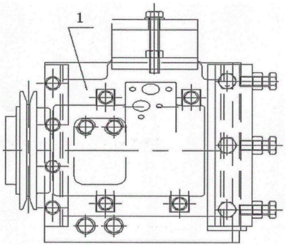
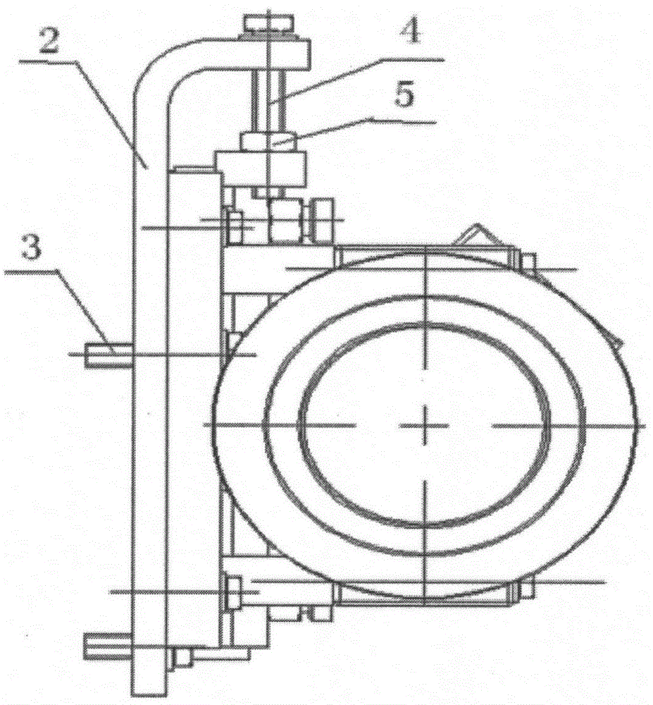
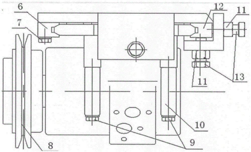
[0030] Such as figure 1 As shown, it is a structural schematic diagram of an air-conditioning compressor fixing and driving belt tensioning device for an excavator. The air-conditioning compressor fixing and driving belt tensioning device for an excavator includes a base 2 and a compressor mounting seat 1, such as figure 2 As shown, the base 2 is locked on the engine through the base fixing bolts 3 to support the entire device. Such as image 3 As shown, the base 2 is provided with Figure 6a and 6b The fixed guide rail 6 and the locking guide rail 12 are shown, the fixed guide rail 6 is fixed on the base 2, the locking guide rail 12 is arranged opposite to the fixed guide rail 6, and the left and right sides of the compressor mounting seat 1 are respectively arranged on On the fixed guide rail 6 and the locking guide rail 12 and can slide longitudinally along the fixed guide rail 6 and the locking guide rail 12, the compressor mounting seat 1 is clamped by the fixing guid...
PUM
 Abstract
Description
Claims
Application Information