

Positioning pin facilitating workpiece cleaning
A technology for positioning pins and workpieces, applied in cleaning methods and tools, chemical instruments and methods, bolts, etc., can solve the problems of unclean cleaning of workpiece pin holes, and achieve the effects of simple structure, stable support, and easy cleaning
- Summary
- Abstract
- Description
- Claims
- Application Information
AI Technical Summary
Problems solved by technology
Method used
Image

Examples
Embodiment Construction
[0019] The present invention will be further described below in conjunction with the accompanying drawings and embodiments.
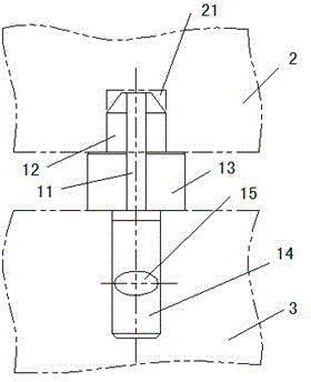
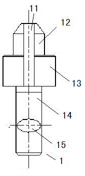
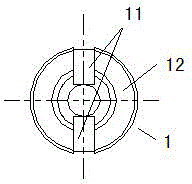
[0020] A positioning pin 1 that facilitates the cleaning of the workpiece 2, such as figure 1 As shown, when in use, the coupling column 14 of the positioning pin 1 is screwed to the clamp 3, and the pin is inserted through the through hole of the clamp 3 into the positioning groove 15 for positioning. After the positioning pin 1 is positioned and connected on the fixture 3, the workpiece 2 to be cleaned is then clamped. When loading, the positioning column 12 is inserted into the pin hole of the workpiece 2 for positioning. The support platform 13 between the positioning column 12 and the connecting column 14 plays a role of supporting and positioning the workpiece 2, and its two end surfaces correspond to the surface of the workpiece 2 and the surface of the fixture 3 to be close together. The thinking of this scheme is to design the channel leading ...
PUM
 Abstract
Description
Claims
Application Information