Indoor unit of air conditioner

An air-conditioning indoor unit and air flow technology, which is applied in air-conditioning systems, space heating and ventilation, heating methods, etc., can solve the problems of large air output noise, eccentric vortex structure backflow, and small air output from the air duct system. Use requirements, increase the wind angle, and expand the effect of the wind range

Inactive Publication Date: 2015-08-12
WUHU MATY AIR CONDITIONING EQUIP CO LTD +1
View PDF4 Cites 0 Cited by
  • Summary
  • Abstract
  • Description
  • Claims
  • Application Information

AI Technical Summary

Problems solved by technology

However, due to the complexity of the internal flow field of the cross-flow fan, its eccentric vortex structure will generate backflow, resulting in a large energy loss, usually making the total efficiency of the cross-flow fan only 10% to 30%.
On the other hand, due to the existence of vortices in the flow field in the cross-flow fan, vortex shedding at the trailing edge of the impeller blades, and pressure fluctuations in the boundary layer, etc., the broadband noise of the cross-flow fan is generated. The load pulsation leads to the generation of discrete noise
The inefficiency of this flow, as well as the issue of noise, has been a constant concern
When the relative position of the volute, volute tongue and the cross-flow wind wheel is not set, it is easy to bring defects such as small air volume and large air output noise to the air duct system

Method used


Image

  • Indoor unit of air conditioner
  • Indoor unit of air conditioner
  • Indoor unit of air conditioner

Examples


Embodiment 1

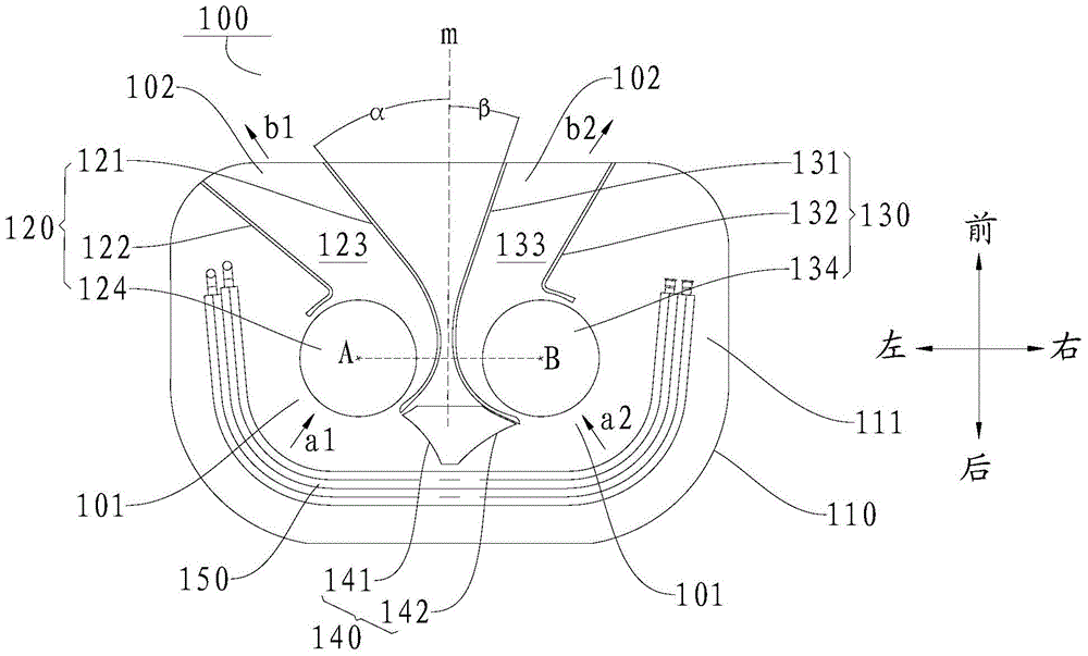
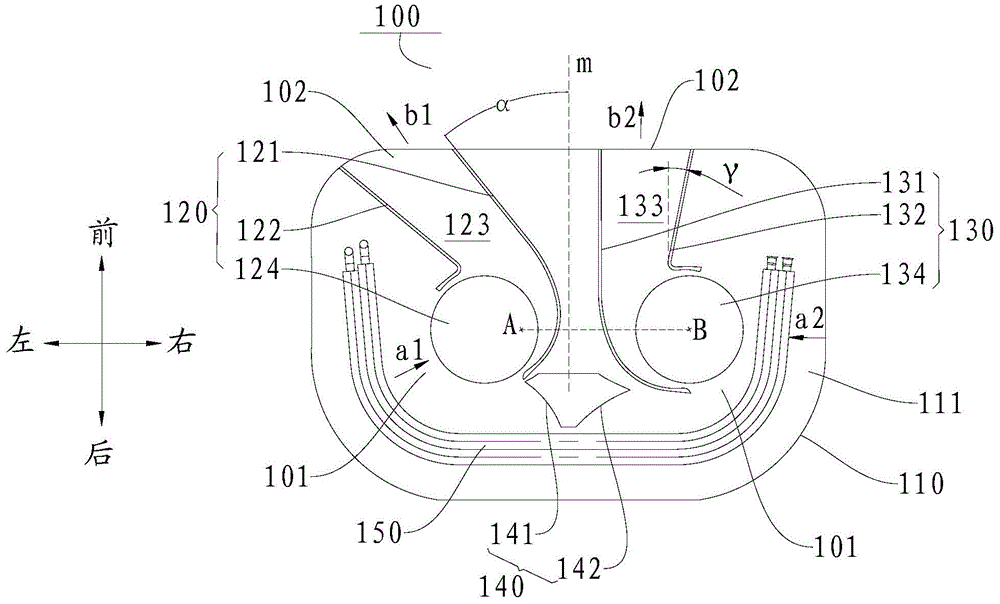
[0052] like figure 1 , figure 2 As shown, in this embodiment, the side wall of the first air duct assembly 120 on the side close to the reference center line is the first volute 121, and the side wall of the second air duct assembly 130 on the side close to the reference center line is the first volute 121. The two volutes 131 , the first air duct 123 and the second air duct 133 are configured so that the air flows discharged from the respective air outlets 102 do not intersect. In this way, the air outlet angle of the air conditioner indoor unit 100 can be expanded to meet the user's needs. like figure 1 , figure 2 As shown, the air will flow along the figure 1 , figure 2 The directions shown by the middle arrows b1 and b2 flow out from the first air passage 123 and the second air passage 133 .

[0053] Further, the air outlet ends of the first volute 121 and the second volute 131 are respectively inclined away from the reference center line. Thus, the structural di...

Embodiment 2

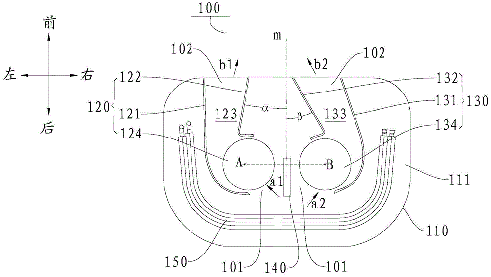
[0056] like image 3As shown, in this embodiment, the side wall of the first air duct assembly 120 near the reference center line is the first volute tongue 122, and the side wall of the second air duct assembly 130 near the reference center line is the first volute tongue 122. The two volute tongues 132 , the first air channel 123 and the second air channel 133 are configured so that the air flows discharged from the respective air outlets 102 intersect. Thus, the air outlet mode of the air conditioner indoor unit 100 can be changed to meet the user's needs.

[0057] Further, the air outlet ends of the first volute tongue 122 and the second volute tongue 132 are inclined towards the reference centerline. In this way, the structural diversity of the air-conditioning indoor unit 100 can be improved, and the air outlet angle of the air-conditioning indoor unit 100 can be changed to meet the needs of users. For example, if image 3 As shown, the air outlet end of the first vol...


PUM


Abstract

The invention discloses an indoor unit of an air conditioner. The indoor unit comprises a shell, a first air duct assembly, a second air duct assembly, a first through-flow wind wheel and a second through-flow wind wheel, wherein the first air duct assembly and the second air duct assembly are arranged in a mounting space, and form a first air duct and a second air duct respectively; both the first air duct and the second air duct are provided with air inlets and air outlets; the first through-flow wind wheel and the second through-flow wind wheel are arranged in parallel in the first air duct and the second air duct; on the cross section of the shell, the midperpendicular of a connection line between the axle centers of the first through-flow wind wheel and the second through-flow wind wheel is taken as a reference center line; the first air duct and the second air duct are asymmetrical relative to the reference center line. According to the indoor unit of the air conditioner, the first air duct and the second air duct which are asymmetrical are defined by the first air duct assembly and the second air duct assembly, so that the air outlet angle of the indoor unit of the air conditioner can be increased, the air outlet range is enlarged, the air conditioner is diversified, and the use demands of different users are met.

Description

technical field [0001] The present invention relates to the technical field of air conditioners, in particular to an air conditioner indoor unit. Background technique [0002] The cross-flow fan has the characteristics of simple structure, small size, high dynamic pressure, and stable airflow. It is widely used in low-pressure ventilation equipment, such as household split wall-mounted air conditioner indoor units. However, due to the complexity of the internal flow field of the cross-flow fan, its eccentric vortex structure will generate backflow, resulting in a large energy loss, usually making the total efficiency of the cross-flow fan only 10% to 30%. On the other hand, due to the existence of vortices in the flow field in the cross-flow fan, vortex shedding at the trailing edge of the impeller blades, and pressure fluctuations in the boundary layer, etc., the broadband noise of the cross-flow fan is generated. The load pulsation leads to the generation of discrete nois...

Claims


Application Information

Patent Timeline
Patent Type & Authority Applications(China)
IPC IPC(8): F24F1/00
CPCF24F1/0003F24F1/0029F24F1/0033F24F13/02
Inventor 闫长林
Owner WUHU MATY AIR CONDITIONING EQUIP CO LTD
Why Eureka
Try Eureka