

Air guide structure and fan
A technology of air guide structure and fan, which is applied to non-variable-capacity pumps, pump components, and components of pumping devices for elastic fluids, etc. The effect of increasing the air supply speed, reducing the collision loss and improving the user experience
- Summary
- Abstract
- Description
- Claims
- Application Information
AI Technical Summary
Problems solved by technology
Method used
Image

Examples
Embodiment 1
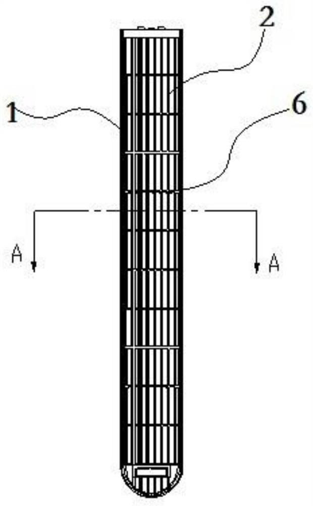
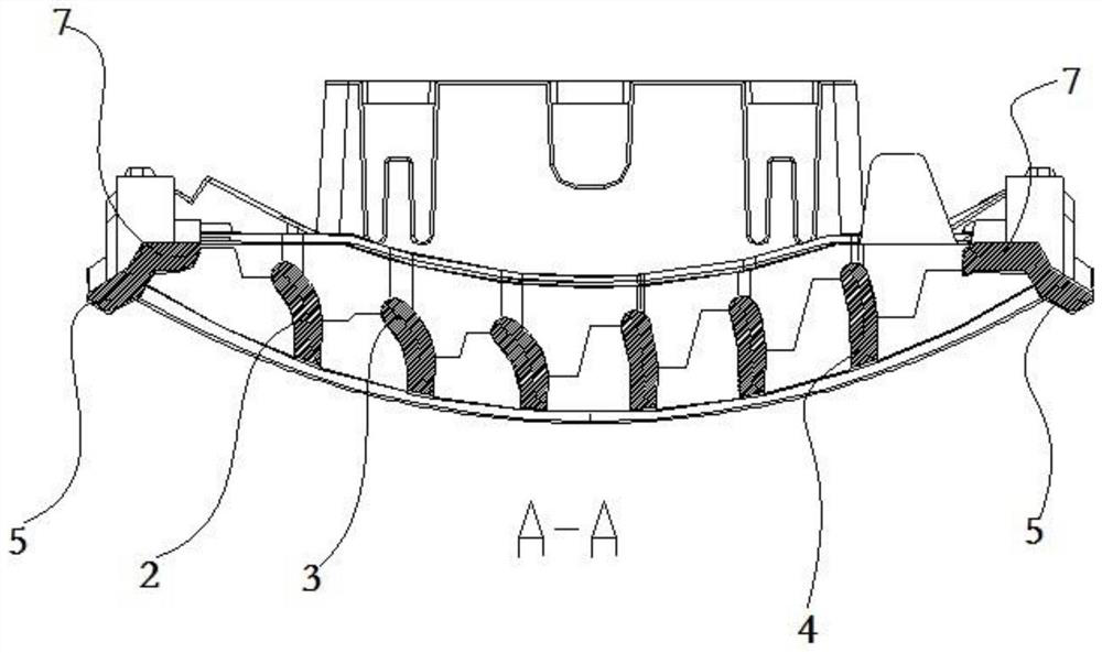
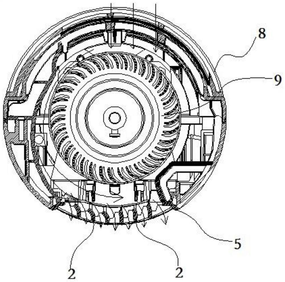
[0041] figure 1 It is a front view of the wind guide structure provided in Embodiment 1 of the present invention; figure 2 for figure 1 A cross-sectional view along the direction A-A of the shown wind guiding structure; image 3 It is a top sectional view of the tower fan provided in Embodiment 1 of the present invention. Such as Figure 1-3As shown, the air guide structure provided by this embodiment includes a frame body 1 and a number of air guide plates 2 arranged in the frame body 1, and the two ends of the air guide plate 2 along its length direction are respectively connected to the frame body 1 One end of each wind deflector 2 along its width direction has a bent portion 3 bent towards the direction of the wind. The wind guide structure, because the airflow blown by the wind source first contacts the bending part 3, the bending part 3 of the wind deflector 2 is bent toward the direction of the incoming wind, reducing the angle between the bending part 3 and the in...
PUM
 Abstract
Description
Claims
Application Information