Guide system for guiding a door leaf

Active Publication Date: 2022-11-08
JULIUS BLUM GMBH
View PDF35 Cites 0 Cited by
  • Summary
  • Abstract
  • Description
  • Claims
  • Application Information

AI Technical Summary

Benefits of technology

[0014]In this way, the kinetic energy of the door wing, upon a transfer from the first guide rail to the carrier, is not dissipated, but rather maintained, at least partially, for a continued movement in a direction of the transversely extending second guide rail. The door wing connected to the guide carriage is guided by the bow-shaped control curve in a direction of the second guide rail, so that the further movement direction of the door wing relative to the second guide rail is predetermined for a continued intuitive movement.
[0018]According to a further embodiment, a locking device for releasably locking the carrier to the adaptor portion can be provided. The locking device can include at least one pivotally mounted actuating lever having a locking position and an unlocking position. The carrier is locked relative to the adaptor portion in the locking position of the actuating lever, and the carrier is unlocked from the adaptor portion in the unlocking position of the actuating lever. The actuating lever in question, starting from the locking position, can be moved from the locking position into the unlocking position by a transfer of the guide carriage from the first guide rail to the carrier, and is configured to be acted upon by the guide carriage, and, as a result, can be moved into the unlocking position.

Problems solved by technology

A drawback with this construction is the fact that the guide element, upon the right-angled transition between the first and second guide rail, can collide with the U-shaped limbs of the guide rails.
As a result, the insertion movement of the cabinet doors into the lateral insertion gap is impeded.
A drawback is the fact that the door wings, in a parallel position to one another, can only be moved with a high manual effort in a direction of the depth of the cabinet.
A drawback is the increased constructional effort and the large space requirement, because a width of the storeroom must be larger than a width of the wall elements.

Method used


Image

  • Guide system for guiding a door leaf
  • Guide system for guiding a door leaf
  • Guide system for guiding a door leaf

Examples


Embodiment Construction

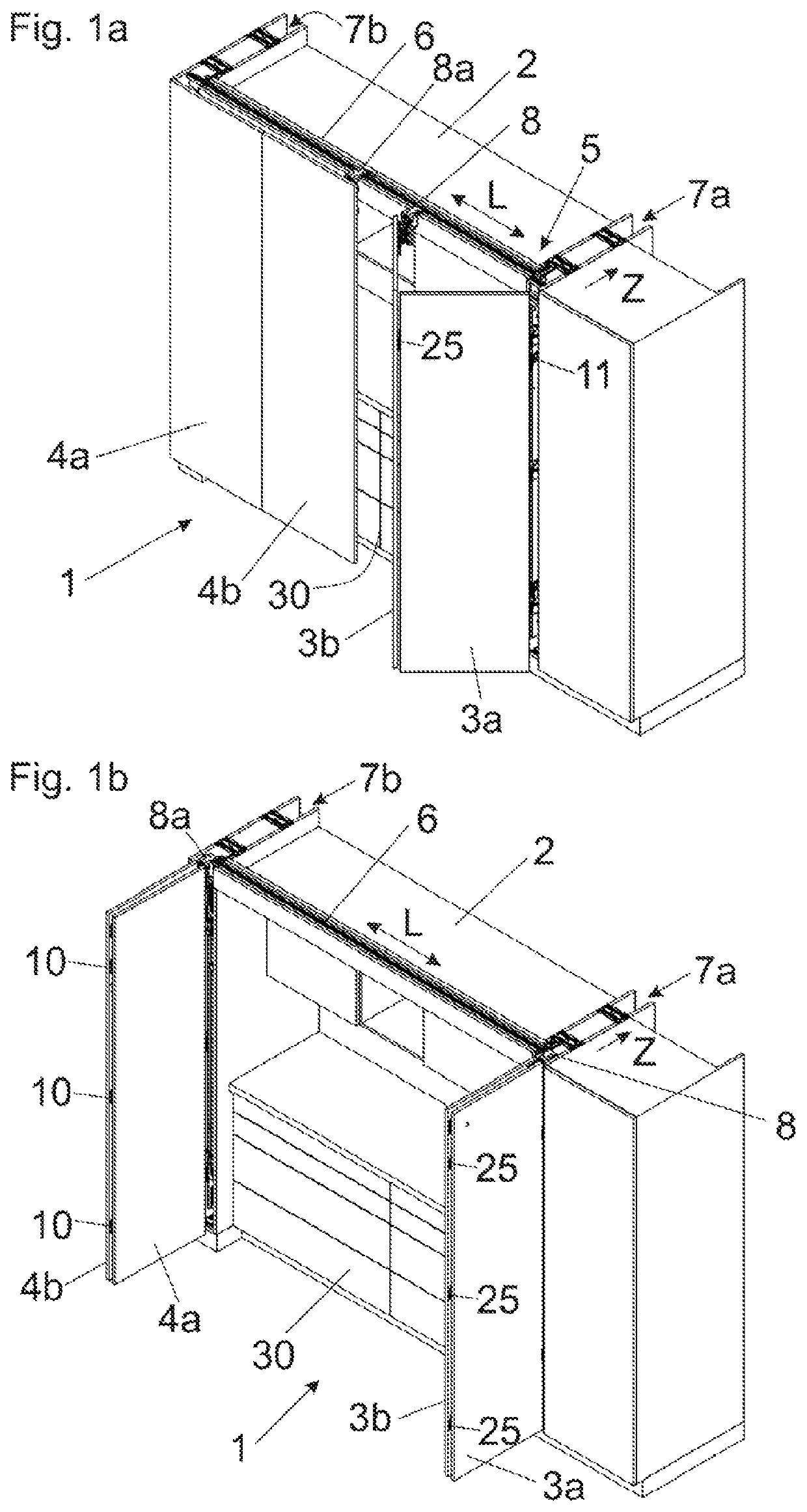
[0032]FIG. 1a shows a perspective view of an item of furniture 1 having door wings 3a, 3b and 4a, 4b configured to be moved by a guide system 5 relative to a furniture carcass 2. The guide system 5 includes a first guide rail 6 having a longitudinal direction (L), and a second guide rail 11 extending transversely, preferably at a right angle, to the longitudinal direction (L) for guiding the door wings 3a, 3b in a direction (Z). A guide carriage 8 connected to the door wing 3b is provided, the guide carriage 8 being configured to be moved along the first guide rail 6 and relative to the second guide rail 11. For example, the first guide rail 6 can rest against an upper side of the furniture carcass 2. The first guide rail 6 and the second guide rail 11 can be spaced from one another in a height direction or can also be arranged at a same height. The door wings 3a, 3b, in a parallel position to one another, can be inserted into a lateral cavity 7a. By a second guide carriage 8a conne...


PUM


Abstract

A guide system includes a first guide rail, a guide carriage configured to be connected to the door wing and configured to run along the first guide rail, a second guide rail separate from the first guide rail, the second guide rail extending transversely to the first guide rail in a mounted condition, a carrier configured to be displaceable relative to the second guide rail, the guide carriage can be arranged on the carrier, and a transfer device for transferring the guide carriage at least from the first guide rail to the carrier. The transfer device includes a control curve configured to be bow-shaped at least over a region, so that the guide carriage, upon a transfer from the first guide rail to the carrier, can be moved at least over a region in a direction of the second guide rail.

Description

BACKGROUND OF THE INVENTION[0001]The present invention relates to a guide system for guiding at least one movably supported door wing, the guide system comprising:[0002]a first guide rail,[0003]at least one guide carriage configured to be connected to the at least one door wing and being configured to run along the first guide rail,[0004]a second guide rail separate from the first guide rail, the second guide rail extending transversely to the first guide rail in a mounted condition,[0005]a carrier configured to be displaceable relative to the second guide rail, the at least one guide carriage can be arranged on the carrier,[0006]a transfer device for transferring the at least one guide carriage at least from the first guide rail to the carrier.[0007]The invention further concerns an arrangement comprising at least one door wing and a guide system of the type to be described. Moreover, the invention relates to an item of furniture comprising such a guide system and / or an arrangement...

Claims


Application Information

Patent Timeline
Patent Type & Authority Patents(United States)
IPC IPC(8): E05D15/58E05D15/26
CPCE05D15/58E05D15/264E05Y2900/212Y10T16/379E06B3/5045E05Y2201/638
Inventor SPERGER, THOMASHOFFMANN, BENJAMINGASSER, INGO
Owner JULIUS BLUM GMBH
Why Eureka
Try Eureka