Circulation heat dissipation module

A technology of circulating heat dissipation and heat source, applied in indirect heat exchangers, lighting and heating equipment, etc., can solve problems such as poor heat exchange between gas and tube wall, and decreased circulating heat dissipation efficiency.

Inactive Publication Date: 2019-10-25
ACER INC
View PDF10 Cites 0 Cited by
  • Summary
  • Abstract
  • Description
  • Claims
  • Application Information

AI Technical Summary

Problems solved by technology

[0004] However, through fluid visualization experiments, it can be found that after the working fluid becomes gas and leaves the evaporator, it will flow in the pipeline in the form of a slug flow. This phenomenon will form a boundary layer on the tube wall, resulting in The heat exchange between the gas and the tube wall is not effective, resulting in a decrease in the heat dissipation efficiency of the cycle

Method used


Image

  • Circulation heat dissipation module
  • Circulation heat dissipation module
  • Circulation heat dissipation module

Examples


Embodiment Construction

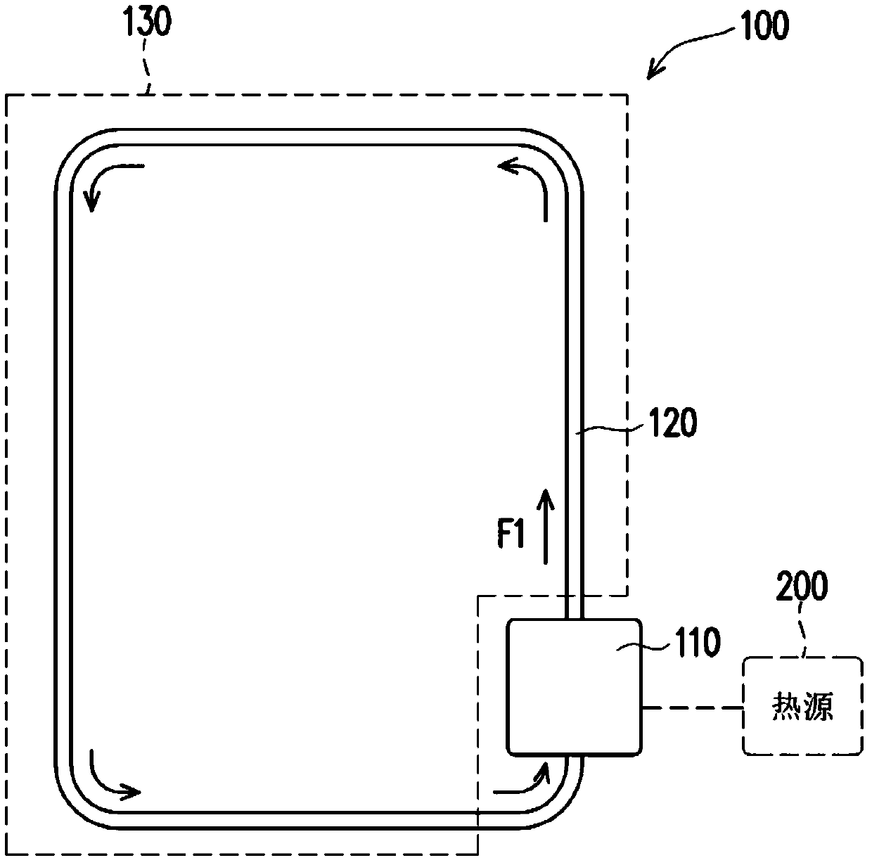
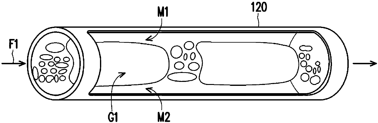
[0038] figure 1 It is a schematic diagram of a circulation cooling module according to an embodiment of the present invention. figure 2 It is the gas and liquid phase state produced when the working fluid passes through the condensation section. Please also refer to figure 1 and figure 2 , in this embodiment, the circulating heat dissipation module 100 is used to dissipate heat from the heat source 200, and the circulating heat dissipation module 100 includes an evaporator 110, a working fluid F1, and a condenser, and the condenser includes a pipe fitting 120 and a heat dissipation plate 130 that are in structural contact with each other , wherein the pipe fitting 120 is connected to the evaporator 110 to form a circuit, so that the working fluid F1 is filled in the circuit, and the liquid and gas phases are transformed by the working fluid F1 due to suction and heat dissipation, so as to achieve the effect of removing the heat generated by the heat source.

[0039] For e...


PUM


Abstract

The invention provides a circulation heat dissipation module. The circulation heat dissipation module is used for heat dissipation of a heat source. The circulation heat dissipation module comprises an evaporator, a condenser and a micro / nano structure, wherein the evaporator is in thermal contact with the heat source so as to absorb the heat generated by the heat source; the condenser is connected with the evaporator and forms a loop, the working fluid fills the loop, the working fluid absorbs heat at the evaporator and is converted into gas from the liquid, and the working fluid is cooled atthe condenser and is converted into liquid from the gas; the micro / nano structure is arranged on the condenser to destroy a boundary layer formed by the working fluid flowing through the condenser.

Description

technical field [0001] The invention relates to a heat dissipation module, in particular to a circulation heat dissipation module. Background technique [0002] The technology of using the latent heat conversion of gas-liquid two-phase change to take away the heat of electronic components has developed a two-phase (liquid, gas) heat dissipation technology. The basic principle is to use the cooling liquid to be heated in the evaporator that is in thermal contact with the heat source The process of vaporization into steam takes a large amount of heat away from the heat source, and the continuous formation of steam will form a thrust to push the heated liquid and steam away from the evaporator, and gradually cool down after heat dissipation, condense into liquid, and then flow back again evaporator to accept the next heat absorption. [0003] In this way, a cycle is formed through heat exchange in the evaporator (working fluid heat absorption) and heat exchange away from the e...

Claims


Application Information

Patent Timeline
Patent Type & Authority Applications(China)
IPC IPC(8): F28D15/02
CPCF28D15/0266
Inventor 郑丞佑廖文能谢铮玟
Owner ACER INC
Why Eureka
Try Eureka