DC boost circuit

A technology of DC power supply and booster circuit, which is applied in the direction of converting DC power input to DC power output, electrical components, and adjusting electrical variables, etc. It can solve problems such as inability to work, unusable, and low power of subsequent equipment

Active Publication Date: 2015-09-23
上海新物科技有限公司
View PDF5 Cites 0 Cited by
  • Summary
  • Abstract
  • Description
  • Claims
  • Application Information

AI Technical Summary

Problems solved by technology

Due to the limited performance of semiconductor components, ordinary DC-DC circuits and charge pump circuits cannot work when facing extremely low voltage input (such as DC voltage lower than 100mV), and cannot raise the input voltage to a suitable level. level to provide power to the load
[0003] In addition, when the power of the front-end power supply is limited, even if the voltage is boosted, the subsequent equipment cannot be used because the power is too low

Method used


Image

  • DC boost circuit
  • DC boost circuit
  • DC boost circuit

Examples


Embodiment Construction

[0021] In order to make the object, technical solution and advantages of the present invention clearer, various embodiments of the present invention will be described in detail below in conjunction with the accompanying drawings. However, those of ordinary skill in the art can understand that, in each implementation manner of the present invention, many technical details are provided for readers to better understand the present application. However, even without these technical details and various changes and modifications based on the following implementation modes, the technical solution claimed in each claim of the present application can be realized.

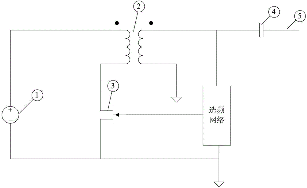
[0022] The first embodiment of the present invention relates to a DC power booster circuit, the specific structure is as follows figure 1 As shown, it includes: a DC power supply, a transformer, an N-channel Junction Field Effect Transistor (JFET for short), a frequency selection network, a coupling capacitor, and an output ...


PUM


Abstract

The invention relates to a boost circuit, and discloses a DC boost circuit. The boost circuit comprises a DC power supply, a transformer, an N trench JFET (junction field-effect transistor), and a frequency selective network. The positive electrode of the DC power supply is connected with a first port of a primary side of the transformer, and the negative electrode of the DC power supply is connected with the source electrode of the N trench JFET. A second port of the primary side is connected with the drain electrode of the N trench JFET. A first port of a secondary side of the transformer is connected with a first port of the frequency selective network, and a second port of the second side is connected with the lowest electric potential of the DC boost circuit. A second port of the frequency selective network is connected with the grid electrode of the N trench JFET, and a third port of the frequency selective network is connected with the lowest electric potential. An output end of the DC boost circuit is connected with the first port of the secondary side of the transformer. Compared with the prior art, the boost circuit can increase an extremely low voltage (less than 100mV) to a proper electric potential, so as to supply power to a load.

Description

technical field [0001] The invention relates to a boost circuit, in particular to a DC power boost circuit. Background technique [0002] At present, common low-voltage boosting circuits use traditional DC (Direct current, direct current)-DC (Direct current, direct current) circuits or charge pump circuits. Due to the limited performance of semiconductor components, ordinary DC-DC circuits and charge pump circuits cannot work when facing extremely low voltage input (such as DC voltage lower than 100mV), and cannot raise the input voltage to a suitable level. level to provide power to the load. [0003] In addition, when the power of the front-end power supply is limited, even if the voltage is boosted, the subsequent equipment cannot be used because the power is too low. Contents of the invention [0004] The purpose of the present invention is to provide a DC power boosting circuit, so that the extremely low voltage (for example, the voltage is lower than 100mV) can be ...

Claims


Application Information

Patent Timeline
Patent Type & Authority Applications(China)
IPC IPC(8): H02M3/335
Inventor 徐吉郑春雷贾根团郑洪渠陈明金军李鹏宇
Owner 上海新物科技有限公司
Why Eureka
Try Eureka