An LC Oscillator with a Tail Current Source and a Transformer-Based Tank Tank

An oscillator-transformer technique for improved clipping and recovery oscillators that can solve problems without significant phase noise improvement

Active Publication Date: 2017-07-14
HUAWEI TECH CO LTD
View PDF1 Cites 0 Cited by
  • Summary
  • Abstract
  • Description
  • Claims
  • Application Information

AI Technical Summary

Problems solved by technology

Therefore, there is no significant phase noise improvement in newer CMOS processes

Method used


Image

  • An LC Oscillator with a Tail Current Source and a Transformer-Based Tank Tank
  • An LC Oscillator with a Tail Current Source and a Transformer-Based Tank Tank
  • An LC Oscillator with a Tail Current Source and a Transformer-Based Tank Tank

Examples


Embodiment Construction

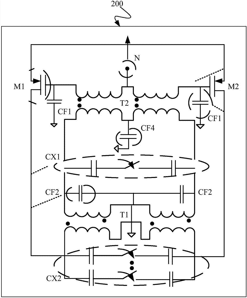
[0107] image 3 is a circuit diagram of oscillator 300 according to one implementation.

[0108] Oscillator 300 includes a pair of transistors 301 and 303 with their sources SOURCEA and SOURCEB interconnected and their drains DRAINA, DRAINB and gates GATEA, GATEB coupled by a positive feedback loop comprising an oscillator tank circuit 309. The sources SOURCEA and SOURCEB of transistors 301 and 303 are connected to a current source 305 configured to control the physical parameters of the oscillator 300 . Current source 305 provides a current or tail current.

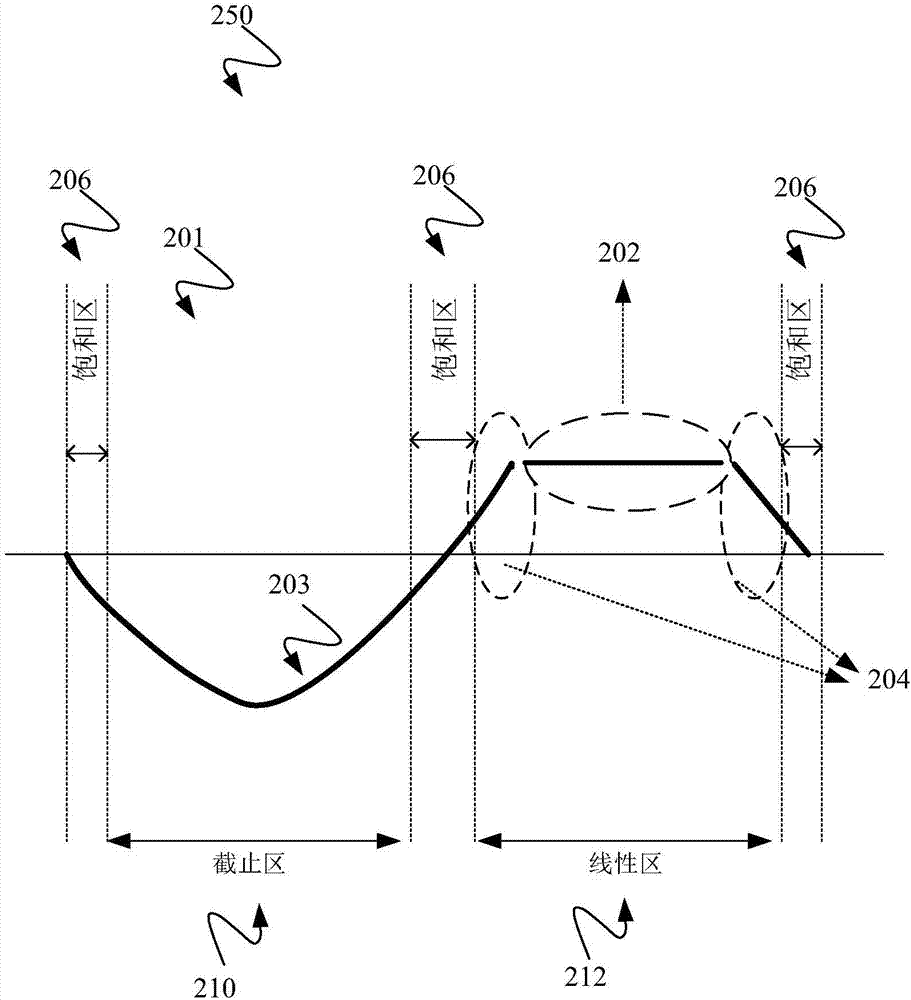
[0109] The current source 305 controls the clipping duration on the oscillating voltage around the oscillator oscillating circuit 309, controls the oscillation amplitude caused by process changes, and satisfies the reliability caused by time-lapse breakdown, hot carrier effect performance deterioration, and drain body breakdown. To solve the problem of stability, the power consumption of the oscillator 300 is adjusted ...


PUM


Abstract

The invention discloses an oscillator (300), comprising: a pair of transistors (301, 303), the sources (SOURCEA, SOURCEB) of which are connected to each other, and the drains (DRAINA, DRAINB) and the gates (GATEA, GATEB) are composed of A positive feedback loop including an oscillator tank circuit (309) is coupled. Wherein, the sources (SOURCEA, SOURCEB) of the transistors (301, 303) are connected to a current source (305) configured to control the physical parameters of the oscillator (300).

Description

technical field [0001] The present invention relates to an oscillator, and more particularly to an improved clipping and recovery oscillator. Background technique [0002] Transceiver architectures rely on the use of local oscillators for frequency translation to generate radio frequency (RF) or intermediate frequency (IF) local signals for upconverting baseband signals to RF signals and vice versa. Therefore, the oscillator is one of the most important components in every wireless system. The performance of the local oscillator has the following effects on the wireless system: [0003] Phase noise is one of the most fatal flaws of wireless systems. Due to the non-ideality of phase noise, it corrupts the information loaded on the carrier phase. Phase noise can create two different types of disruptions in a system. One is from the in-band, that is, the out-of-band phase noise of the modulating signal. This directly affects the downconverted, or upconverted, signal. In a...

Claims


Application Information

Patent Timeline
Patent Type & Authority Patents(China)
IPC IPC(8): H03B5/12
CPCH03B5/1228H03B5/1296H03B5/1215H03B2200/0036H03B2200/0048H03B2200/0062H03B2200/007H03B2200/0082H03B5/1265H03B5/124H03H11/0405H03L7/06
Inventor 罗伯特·博丹·斯达世斯基马苏德·巴巴伊阿克希·韦斯文斯瓦润何卓彪
Owner HUAWEI TECH CO LTD
Why Eureka
Try Eureka