Maglev curved track beam mechanical formwork system and using method
What is AI technical title?
AI technical title is built by Patsnap AI team. It summarizes the technical point description of the patent document.
A curved track and mechanical technology, applied in the direction of molds, ceramic molding machines, mold auxiliary parts, etc., can solve the problems of low splicing efficiency and poor reliability, and achieve the effect of improving prefabrication efficiency, low cost and high precision
Active Publication Date: 2018-02-13
CHINA RAILWAY 23RD CONSTR BUREAU LTD
View PDF7 Cites 0 Cited by
Summary
Abstract
Description
Claims
Application Information
AI Technical Summary
This helps you quickly interpret patents by identifying the three key elements:
Problems solved by technology
Method used
Benefits of technology
Problems solved by technology
[0004] The purpose of the present invention is to overcome the above-mentioned problems of low splicing efficiency and poor reliability that exist in the prior art when the existing steel formwork system is used to prefabricate curved track beams, through the prefabrication of several sections of linear track beam units, and then splicing. Insufficient, provide a magnetically levitated curved track beam mechanical formwork system, and also provide a method for using the magnetically levitated curved track beam mechanical formwork
Method used
Image
Click on the blue label to locate the original text in one second.
Reading with bidirectional positioning of images and text.
Examples
Embodiment 1
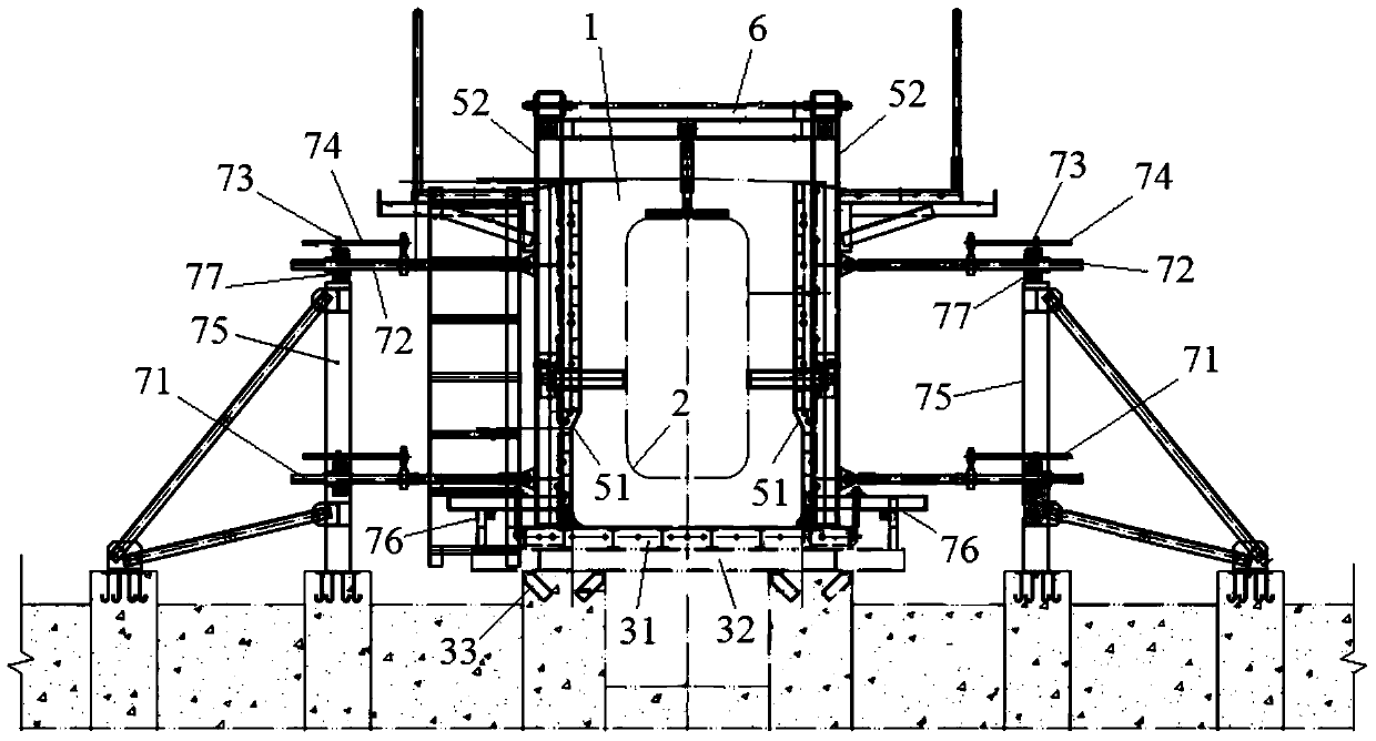
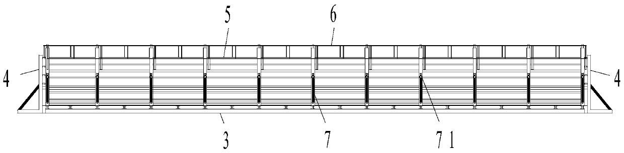
[0052] Such as Figure 1-3 As shown, a maglev curved track beam mechanical formwork system includes:
[0053] Bottom form 3, used for carrying track beam 1;
[0054] The side form 5 includes bendable side form panels 51 arranged along the longitudinal sides of the track beam 1, and several skeletons 52 are arranged on the outside of each side form panel 51;
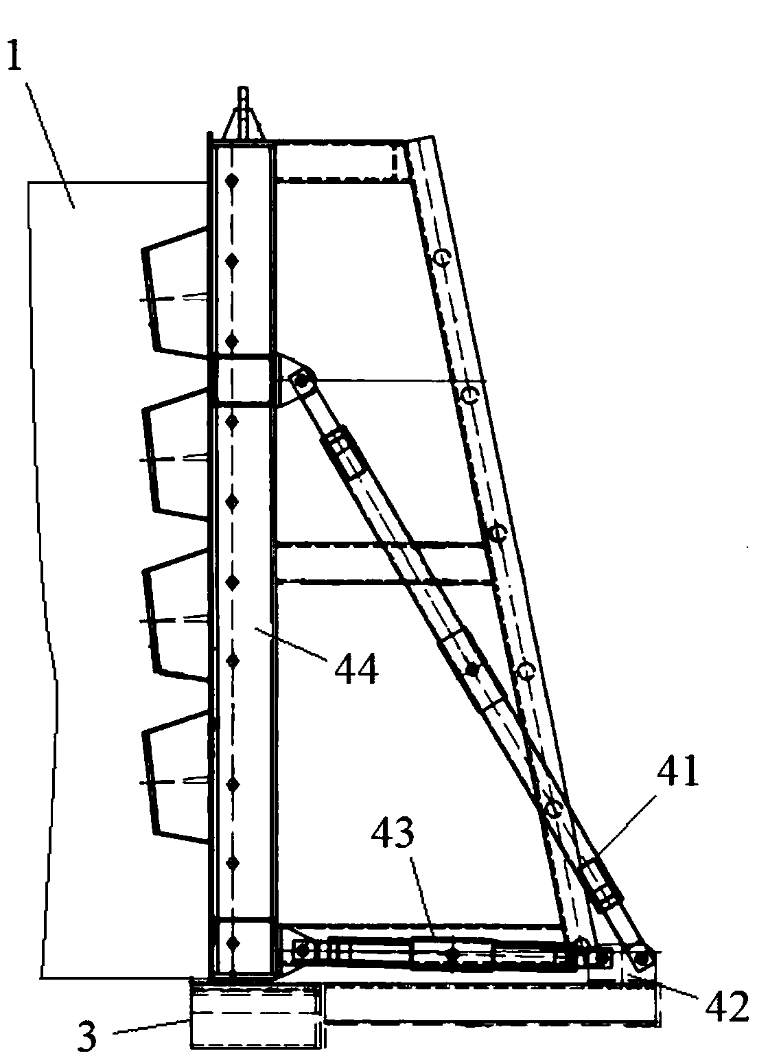
[0055] The end mold 4 is arranged along the two ends of the track beam 1, and the outer side of the end mold 4 is provided with a translation assembly 43 capable of longitudinally translating the end mold 4 along the track beam 1;
[0056] And the adjustment part 7, including at least two mechanical push rod assemblies 71 arranged on the outside of each frame 52, each mechanical push rod assembly 71 is used to adjust the lateral displacement of the corresponding frame 52 relative to the track beam 1 and the verticality relative to the bottom mold 3 .
[0057] Such as figure 1 , 4 As shown, each of the above-mentioned...
Embodiment 2
[0065] Such as Figure 1-5 As shown, the present invention also provides a method for using the maglev curved track beam mechanical formwork system, including the maglev curved track beam mechanical formwork system in Example 1, and the use method includes the following steps:
[0066] Step 1, install the base form 3, and install the base form 3 at the beam making site;
[0067] Step 2, install the side form 5, weld all the skeletons 52 on the side mold panel 51, connect the adjustment parts 7 on the skeleton 52, that is, install at least two mechanical push rod assemblies 71 on each of the skeletons 52;
[0068] Step 3, adjusting the curvature of the side mold 5, adjusting each of the mechanical push rod assemblies 71, so that the skeleton 52 corresponding to each of the mechanical push rod assemblies 71 is laterally displaced or rotated relative to the bottom mold 3, so that The skeleton 52 meets the position of the accuracy requirement, so that the entire side form panel 5...
PUM
Property
Measurement
Unit
surface smoothness
aaaaa
aaaaa
Abstract
The invention discloses a mechanical template system of a curved magnetic levitation track beam and an application method of the mechanical template system. The mechanical template system comprises a bottom template, a lateral template, end templates and a plurality of regulating components, wherein the bottom template is used for bearing the track beam; the lateral template comprises bendable lateral template panels, the bendable lateral template panels are arranged along two longitudinal sides of the track beam, and a plurality of frameworks are arranged on the outer side of each lateral template panel; the end templates are arranged along the end part of the track beam, and each of the end templates is provided with a translation assembly which can translate the end templates along the track beam in the longitudinal direction; each regulating component comprises at least two mechanical push rod assemblies arranged on the outer side of each framework, and each mechanical push rod assembly is used for regulating the lateral displacement of the corresponding framework relative to the track beam and the perpendicularity of the corresponding framework relative to the bottom template. The template system comprises the bottom template, the lateral template, the end templates, a plurality of the regulating components and the translation assemblies, and is simple in structure, high in regulating efficiency and convenient to mount and dismount; after a template curve is regulated and formed, concrete is directly poured so as to form the track beam, so that the prefabricated efficiency of the track beam is improved; the application method is simple, high in accuracy and good in reliability, so that the prefabricated quality of the track beam is ensured.
Description
technical field [0001] The invention relates to the field of bridge design and construction, in particular to a mechanical formwork system for a maglev curved track beam and a method for using it. Background technique [0002] A formwork system is required for existing prefabricated track beams, and the formwork system mainly includes a concrete foundation, left and right concrete reaction walls, a steel formwork system and a track beam transportation system. Among them, the steel formwork system includes side formwork, end formwork, bottom formwork, top beam, spreader, and mechanical jack. Its structure is that the bottom formwork in the steel formwork system is placed on the top surface of the bottom formwork trolley, the end formwork is placed on the bottom formwork, the mechanical jack is installed on the concrete reaction wall, the hanger is installed on the top beam, and the side formwork It is located under the spreader and connected with mechanical jacks respectivel...
Claims
Application Information
Patent Timeline
Application Date:The date an application was filed.
Publication Date:The date a patent or application was officially published.
First Publication Date:The earliest publication date of a patent with the same application number.
Issue Date:Publication date of the patent grant document.
PCT Entry Date:The Entry date of PCT National Phase.
Estimated Expiry Date:The statutory expiry date of a patent right according to the Patent Law, and it is the longest term of protection that the patent right can achieve without the termination of the patent right due to other reasons(Term extension factor has been taken into account ).
Invalid Date:Actual expiry date is based on effective date or publication date of legal transaction data of invalid patent.

