High-resolution implantable micro-vibration monitoring implementation method

A vibration monitoring and high-resolution technology, applied in measuring devices, measuring ultrasonic/sonic/infrasonic waves, instruments, etc., can solve problems such as economic bottlenecks, high team requirements, and expensive monitoring components, and achieve high efficiency of data processing platforms , high accuracy of data acquisition, and the effect of stabilizing DC power supply requirements

Inactive Publication Date: 2015-12-23
CHINA ELECTRONICS ENG DESIGN INST
View PDF10 Cites 2 Cited by
  • Summary
  • Abstract
  • Description
  • Claims
  • Application Information

AI Technical Summary

Problems solved by technology

[0003] (1) The vibration control object is small in size and light in weight, and conventional monitoring methods themselves will generate vibration interference, which is not conducive to vibration control;
[0004] (2) The level of vibration control is relatively high, and the development of micro-vibration monitoring technology is difficult. Mechanical and electrical processing, mechanical engineering, engineering mechanics, vibration control, software development and other majors have higher requirements for professional development personnel and teams
[0005] (3) There is an economic bottleneck in the initial installation stage
At present, the vibration control market is mainly ori...

Method used


Image

  • High-resolution implantable micro-vibration monitoring implementation method
  • High-resolution implantable micro-vibration monitoring implementation method

Examples


Embodiment Construction

[0035] The present invention will be described in further detail below in conjunction with the accompanying drawings and specific embodiments, but not as a limitation of the present invention.

[0036] The invention is mainly oriented to micro-vibration control engineering, involving fields including electronics industry, precision manufacturing, aerospace, astronomical optics, military weapons, etc. The main requirement of micro-vibration control engineering in these industries is that the vibration level of the vibration control object is as high as sub-micron level, the controlled object is small in size, light in weight, and has the characteristics of long-term continuous operation, so the vibration control process needs Continuous monitoring is carried out while also ensuring that the monitoring process itself does not have adverse vibration effects.

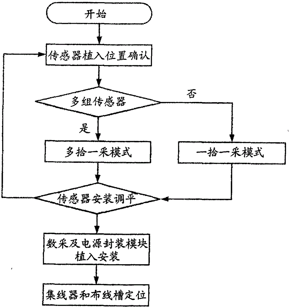
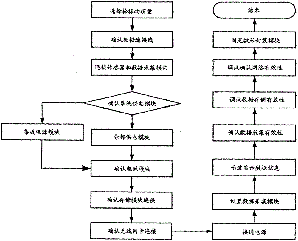
[0037] figure 1 It is a flowchart of the implementation stage of the MEMs sensor and data acquisition configuration modu...


PUM


Abstract

The invention discloses a high-resolution implantable micro-vibration monitoring implementation method. Through selection of a high-resolution small-size micro-vibration pickup and combined with a high speed storage and wireless signal sending technology, various devices are subjected to optimal configuration, a power supply mode is subjected to secondary development and processing, and monitoring of an object needing long-time measurement during the micro-vibration engineering is achieved. The technology has engineering characteristics of small size, light weight and easy implantation aimed to the micro-vibration monitoring engineering, has characteristics of wide effective measuring frequency band, good stability, high data collection precision, high-speed storage and transmission, efficient data processing platform and the like, and has high device matching configuration advantages. An independent power supply module is arranged and branch-type power supply and integrated-type power supply can be achieved, and direct current power supply requirements of various devices during the monitoring process can be met efficiently and stably. The provided method has good economical efficiency and suitable for technology popularization and application.

Description

technical field [0001] The invention belongs to the field of high-precision micro-vibration control engineering and monitoring engineering, and in particular relates to a high-resolution implantable micro-vibration monitoring implementation method. Background technique [0002] At present, targeted and mature micro-vibration monitoring technology and products have not yet appeared. The main reasons include three aspects: [0003] (1) The vibration control object is small in size and light in weight, and conventional monitoring methods themselves will generate vibration interference, which is not conducive to vibration control; [0004] (2) The level of vibration control is relatively high, and the development of micro-vibration monitoring technology is difficult. Mechanical and electrical processing, mechanical engineering, engineering mechanics, vibration control, software development and other majors have high requirements for professional development personnel and teams....

Claims


Application Information

Patent Timeline
IPC IPC(8): G01H11/06
Inventor 胡明祎马新生娄宇邢云林秦敬伟王延伟
Owner CHINA ELECTRONICS ENG DESIGN INST
Why Eureka
Try Eureka