
A kind of z-pin reinforced composite grid structure and its manufacturing method
A technology for reinforcing composite materials and grid structures, which is applied in the field of composite material reinforcement, can solve problems such as strength reduction at joints, and achieve the effects of improving uneven thickness, connection strength and fatigue resistance.
- Summary
- Abstract
- Description
- Claims
- Application Information
AI Technical Summary
Problems solved by technology
Method used
Image

Examples
no. 1 example
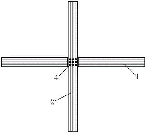
[0035] The first embodiment: such as figure 2 As shown,
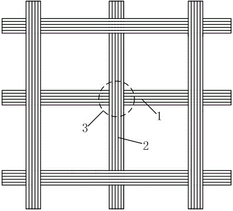
[0036] The Z-pin reinforced composite grid structure of the present invention includes transverse ribs 1 and longitudinal ribs 2, and nodes 3 are formed at the intersection of transverse ribs 1 and longitudinal ribs 2, wherein: transverse ribs 1 and longitudinal ribs 2 adopt “cutting-continuous laying” in turn The process is to lay up, and at the intersection, node 3, implant Z-pin 4 to improve the connection strength of the composite grid structure;
[0037] The "cut-continuous paving" process is: in each layer of composite grid structure, only one of the transverse ribs 1 and longitudinal ribs 2 is laid on the node, and the other is cut on both sides of the node, so that the thickness of each node is the same as that of the transverse rib 1. , The thickness of the rest of the longitudinal rib 2 is the same.
[0038] In the embodiment, the Z-pin 4 implantation direction is perpendicular to the surface of the node 3 formed b...
no. 2 example
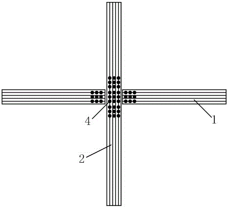
[0051] The second embodiment: such as image 3 As shown,
[0052] In the embodiment, the Z-pin 4 is also implanted in the position near the node 3 on the transverse rib 1 and the longitudinal rib 2.
[0053] The undescribed parts are the same as the first embodiment.
[0054] Compared with the first embodiment, this embodiment has more Z-pin 4 implanted, a wider range, and higher connection strength.
no. 3 example
[0055] The third embodiment: such as Figure 4 As shown,
[0056] In the embodiment, the angle formed by the node 3 and the transverse rib 1 and the longitudinal rib 2 is covered with the same material as the transverse rib 1 and the longitudinal rib 2 to form a reinforcing plate 5.
[0057] The undescribed parts are the same as in the second embodiment.
[0058] Compared with the second embodiment, compared with the first embodiment, this embodiment adds a reinforcing plate 5 to further enhance the connection strength at the nodes.
PUM
 Abstract
Description
Claims
Application Information