A Traffic Conflict Recognition Method Based on Driver's Eye Movement Features

A traffic conflict and recognition method technology, applied in the direction of acquisition/recognition of eyes, character and pattern recognition, instruments, etc., can solve the difference in driver perception results, unfavorable road safety, objective evaluation of traffic system rational planning, and no traffic conflict recognition method found and other issues to achieve the effect of improving consistency and overcoming subjective defects

Inactive Publication Date: 2018-06-19
JILIN UNIV
View PDF3 Cites 0 Cited by
  • Summary
  • Abstract
  • Description
  • Claims
  • Application Information

AI Technical Summary

Problems solved by technology

[0002] Traffic conflict technology is the mainstream of current road traffic safety evaluation methods. Many experts and scholars have proposed many methods in conventional traffic conflict discrimination. "Method" (CN 103106811 A), "A Method and System for Identifying Accident-Prone Road Sections by Using Traffic Conflicts" (CN 103971519A) filed by Southeast University and the Traffic Management Bureau of Nanjing Municipal Public Security Bureau in 2014. Distance, relative speed and their derivative parameters are used as indicators for traffic conflict identification, resulting in a large difference between the results of traffic conflict discrimination and the driver's perception results, which is not conducive to the objective evaluation of road safety and the rational planning of the traffic system
[0003] The widely recognized theory of road traffic design points out that the traffic demand and physiological-psychological response characteristics of road users should be taken as the theoretical basis of road design. Safety evaluation, road design and optimization based on road users' physiological-psychological response characteristics cannot be realized. The reason is that there is no traffic conflict quantitative index that reflects the driver's psychological load and a traffic conflict identification method based on this index.

Method used


Image

  • A Traffic Conflict Recognition Method Based on Driver's Eye Movement Features
  • A Traffic Conflict Recognition Method Based on Driver's Eye Movement Features
  • A Traffic Conflict Recognition Method Based on Driver's Eye Movement Features

Examples


Embodiment Construction

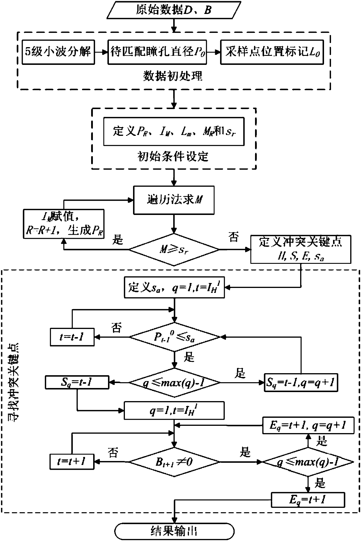
[0036] The traffic conflict recognition method based on the driver's eye movement characteristics of the present invention, such as figure 1 As shown, it specifically includes the following steps:

[0037] Step 1. Data collection

[0038]

[0039] Step 2. Identify the initial pupil diameter data P to be matched 0 P 0 The set of sampling point data serial numbers in is I 0 ,

[0040] Step 3. Use the initial pupil diameter data to be matched Iterate for the initial condition, let the Rth iteration result be R is a natural number; use the traversal method in P R Search the maximum value of pupil diameter peak point M in traffic conflicts R , if M R ≥s r ,s r is the smallest peak pupil diameter in known conflicts, set the maximum value M R Corresponding P 0 The serial number of the sampling point data in is denoted as from P R Remove from arrive data, generate the R+1th iteration result to be matched pupil diameter data P R+1 , let R=R+1; L M is the num...


PUM


Abstract

The present invention relates to a traffic conflict recognition method based on the driver's eye movement characteristics, the method is as follows: collect all pupil diameter data and blinking action data of the driver when driving on the entire virtual design road; identify the initial pupil diameter data to be matched The peak point of the pupil diameter peak of each traffic conflict in the traffic conflict is used as the initial condition to iterate, and the maximum value set of the pupil diameter peak point of the traffic conflict is obtained; The first blink point is used for positioning; the two positioning points are the starting point and the ending point of the traffic conflict. The present invention conforms to the principle of taking road users' traffic demands and physiological-psychological response characteristics as the theoretical basis of road design. Alignment design, traffic system planning rationality puts forward a new method.

Description

technical field [0001] The invention relates to a traffic conflict identification method based on the driver's pupil diameter, and relates to the field of driver's visual behavior and the technical field of traffic conflict in traffic engineering. Background technique [0002] Traffic conflict technology is the mainstream of current road traffic safety evaluation methods. Many experts and scholars have proposed many methods in conventional traffic conflict discrimination. "Method" (CN 103106811 A), "A Method and System for Identifying Accident-Prone Road Sections by Using Traffic Conflicts" (CN 103971519A) filed by Southeast University and the Traffic Management Bureau of Nanjing Municipal Public Security Bureau in 2014. Distance, relative speed and their derivative parameters are used as indicators for traffic conflict identification, resulting in a large difference between the results of traffic conflict discrimination and the driver's perception results, which is not cond...

Claims


Application Information

Patent Timeline
Patent Type & Authority Patents(China)
IPC IPC(8): G06K9/00
CPCG06V40/18G06V40/193G06V20/597
Inventor 李世武徐艺杨志发王琳虹孙文财郭梦竹柴萌魏雨浓
Owner JILIN UNIV
Why Eureka
Try Eureka