Design method of well cementation annulus slurry column structure

A design method and technology of slurry column structure, which are applied in earth-moving drilling, wellbore/well components, sealing/packing, etc., can solve the problem of incomplete consideration of factors affecting cementing annular slurry column pressure, and achieve convenient scheme design It can be mastered by on-site construction personnel, the design results are accurate, and the calculation process is simple.

Active Publication Date: 2016-02-03
PETROCHINA CO LTD
View PDF5 Cites 10 Cited by
  • Summary
  • Abstract
  • Description
  • Claims
  • Application Information

AI Technical Summary

Problems solved by technology

[0004] This application provides a design method for the structure of the cementing annular slurry column, which solves the tec...

Method used


Image

  • Design method of well cementation annulus slurry column structure
  • Design method of well cementation annulus slurry column structure
  • Design method of well cementation annulus slurry column structure

Examples


example 1

[0080] Example 1: Taking Well XX-1 as an example, the application of the present invention is described in detail.

[0081] Well XX-1 is a vertical well with a drilling depth of 3000m and a drilling fluid density of 1.20g / cm 3 , the fracture (leakage) pressure of the formation is 54.9PMa, the well section of the oil and gas layer is 2700m-3000m, the cement is required to return to a depth of 2000m, and the annular friction when the cementing construction is replaced in place is 1.5MPa, and the design of the cementing annular slurry is reasonable column structure.

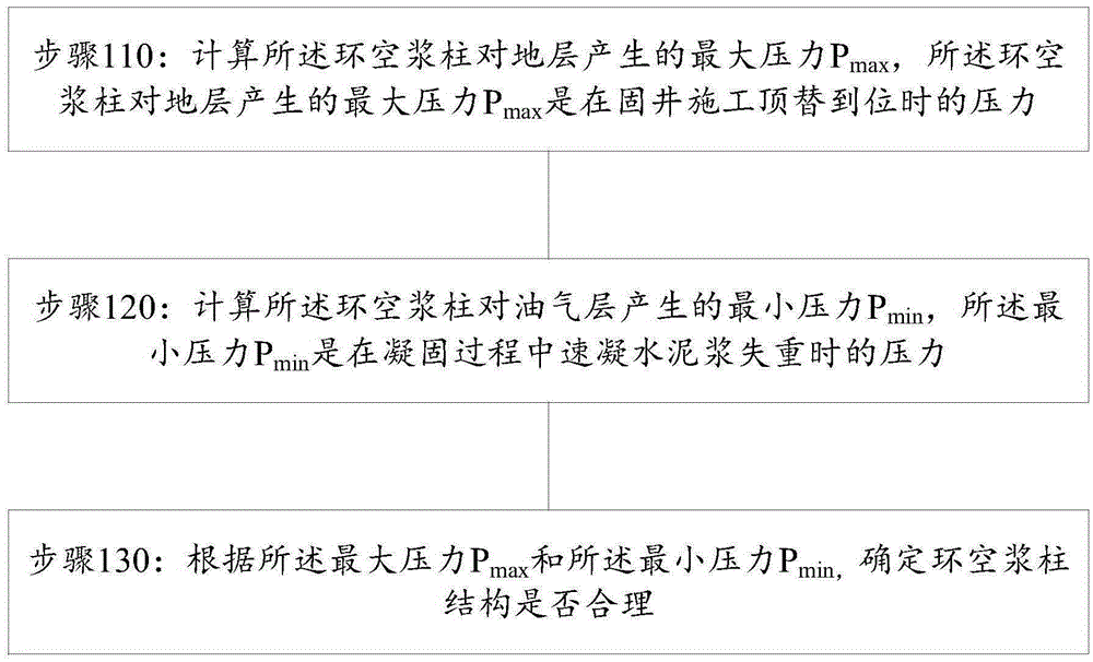
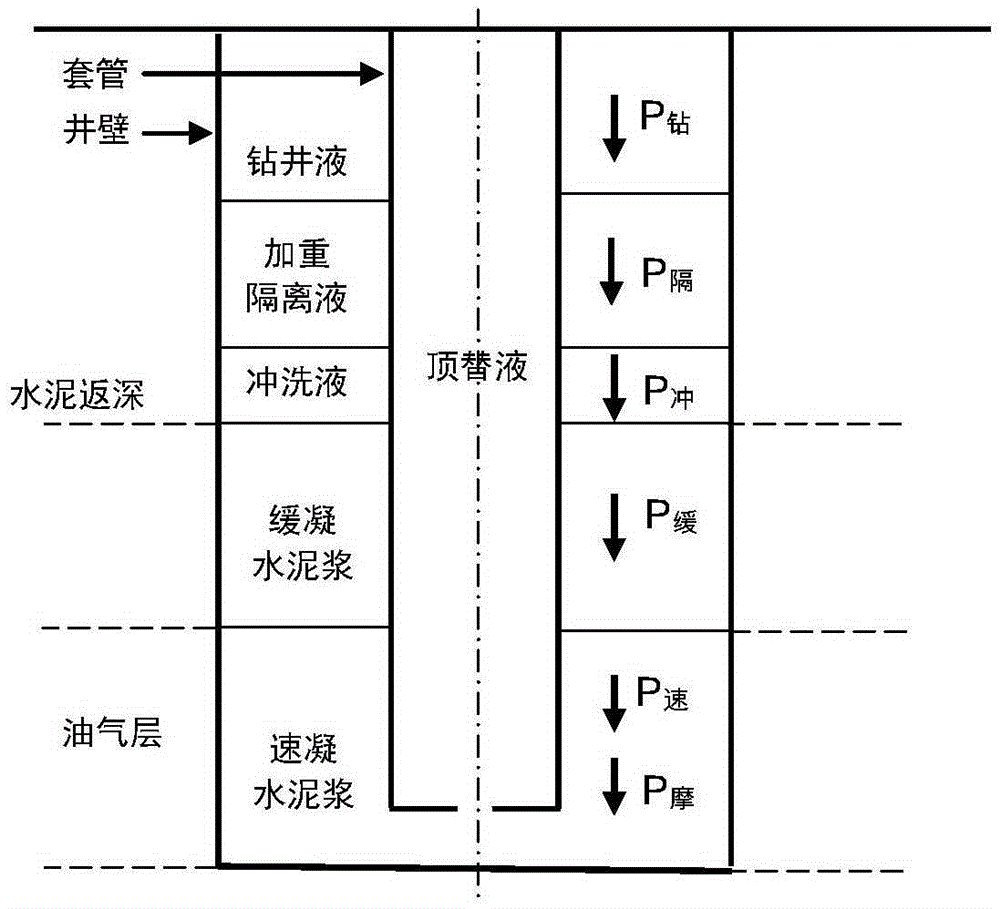
[0082] Step 1: Determine the maximum pressure generated by the slurry column on the formation when the displacement is in place.

[0083] 1. Hydrostatic column pressure of quick-setting cement slurry: 1.90g / cm for quick-setting cement slurry 3 The conventional density, the height is 3000m-2700m=300m.

[0084] P 速 =1.90g / cm 3 ×300m×9.8m / s=5.59MPa

[0085] 2. Hydrostatic column pressure of retarded cement slurry...

example 2

[0106] Example 2: Taking well XX-2 as an example, the application of the present invention is described in detail.

[0107] Well XX-2 is a vertical well with a drilling depth of 3800m and a drilling fluid density of 1.40g / cm 3 , the fracture (leakage) pressure of the formation is 69.5PMa, the well section of the oil and gas layer is 3000m-3800m, the cement is required to return to a depth of 2500m, and the annular friction resistance when the cementing construction is replaced in place is 2.0MPa, and the design of the cementing annular slurry is reasonable column structure.

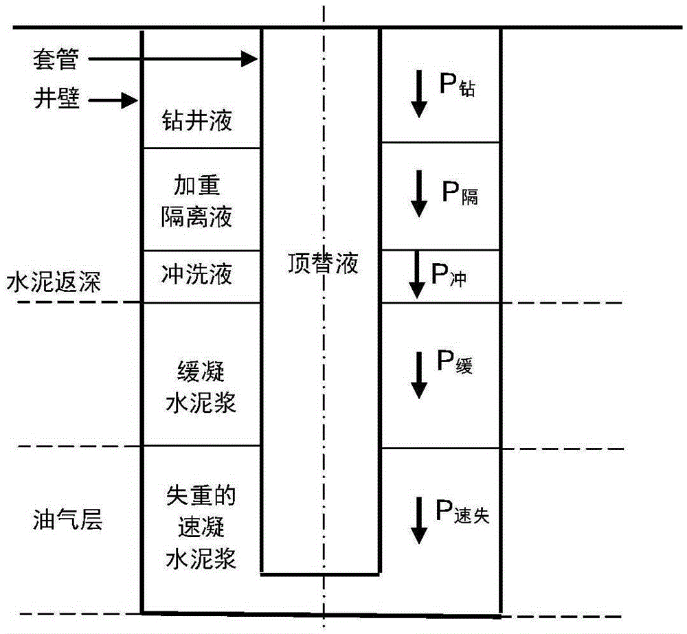
[0108] Step 1: Determine the maximum pressure generated by the slurry column on the formation when the displacement is in place

[0109] 1. Hydrostatic column pressure of quick-setting cement slurry: 1.90g / cm for quick-setting cement slurry 3 The conventional density, the height is 3800m-3000m=800m.

[0110] P 速 =1.90g / cm 3 ×800m×9.8m / s=14.90MPa

[0111] 2. Hydrostatic column pressure of retarded ce...


PUM

PropertyMeasurementUnit
Densityaaaaaaaaaa
Heightaaaaaaaaaa
Densityaaaaaaaaaa

Abstract

The invention discloses a design method of a well cementation annulus slurry column structure. The design method comprises following steps: calculating the maximum pressure Pmax applied on the stratum by an annulus slurry column, wherein the maximum pressure Pmax is the pressure generated when the slurry is displaced in place during the well cementation construction; calculating the minimum pressure Pmin applied on an oil gas bed by the annulus slurry column, wherein the minimum pressure Pmin is the pressure generated when the rapidly cemented cement slurry loses weight during a cementing process; and determining whether the annulus slurry column structure is reasonable according to the maximum pressure Pmax and the minimum pressure Pmin. According to the design method, various pressures related to the annulus slurry column structure can be quantitatively calculated and contrasted, and the determined slurry column structure can stably press the oil gas bed and can prevent the leakage of the stratum. The design method is more scientific and reasonable.

Description

technical field [0001] The invention relates to the technical field of oil and gas development, in particular to a design method for a cementing annular slurry column structure. Background technique [0002] During the cementing process, the drilling fluid, weighted spacer fluid, flushing fluid, slow-setting cement slurry, quick-setting cement slurry and other slurries in the annular space between the casing and the well wall constitute the cementing annular slurry column structure. The density and height of the slurry are different, and the hydrostatic column pressure is also different. In the process of cementing replacement construction, due to the influence of annular friction, a pressure on the formation will be generated; in the process of solidification of quick-setting cement slurry, due to the weightlessness of the cement slurry in the hydration process, the hydrostatic column pressure will be Reduced, the pressure on the formation will be reduced. The pressure ge...

Claims


Application Information

Patent Timeline
IPC IPC(8): E21B33/13
Inventor 唐世忠吴华王海滨董云龙李显涛张晓峰曹磊陈鹏
Owner PETROCHINA CO LTD
Why Eureka
Try Eureka